
HDP-CVD seasoning process for high power HDP-CVD gapfil to improve particle performance

a technology of hdpcvd and seasoning process, which is applied in the direction of coating, chemical vapor deposition coating, semiconductor devices, etc., can solve the problems of damage to the chamber, adversely affecting the yield of wafers, and unwanted deposition on the walls

Inactive Publication Date: 2006-09-19
APPLIED MATERIALS INC
View PDF14 Cites 367 Cited by
  • Summary
  • Abstract
  • Description
  • Claims
  • Application Information

AI Technical Summary

Benefits of technology

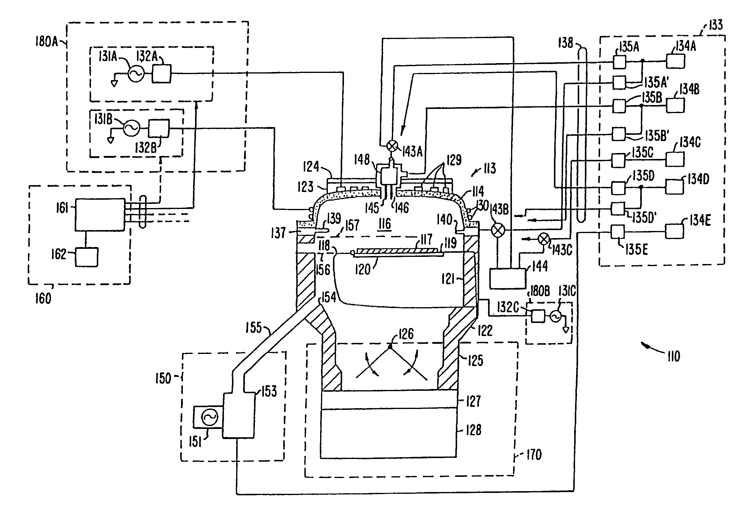
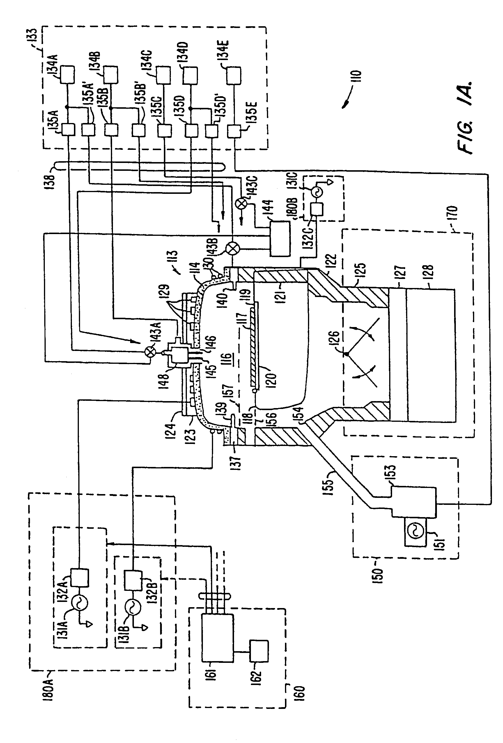
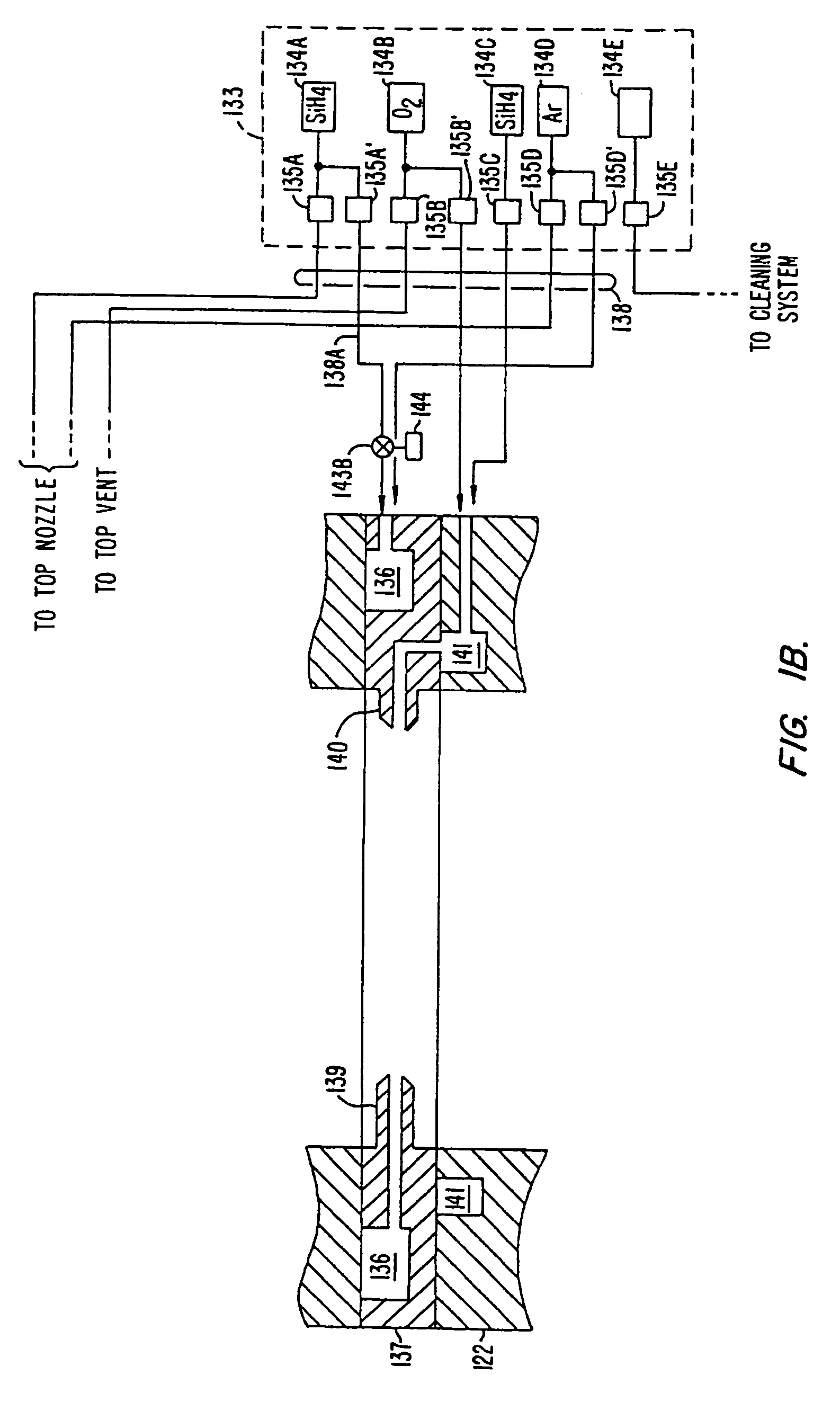
The invention relates to a method and system for processing substrates in a vacuum chamber. The method includes flowing a seasoning gas containing silane and oxygen into the chamber to deposit a silicon oxide film on the chamber's surfaces, particularly on aluminum nitride nozzles. This helps to prepare the chamber for subsequent substrate processing operations. The system includes a housing for forming a vacuum chamber, a gas delivery system with aluminum nitride nozzles, and a controller for controlling the gas delivery system. The invention also includes a computer-readable program for controlling the gas delivery system. The technical effects of the invention include improving the quality and efficiency of substrate processing operations.

Problems solved by technology

During chemical vapor deposition (CVD) of silicon oxide and other layers onto the surface of a substrate, the deposition gases released inside the processing chamber may cause unwanted deposition on areas such as the walls of the processing chamber.
Unless removed, this unwanted deposition is a source of particles that may interfere with subsequent processing steps and adversely affect wafer yield.
This discharging can damage the chamber by ablating away parts of the conductive surface.
As device sizes become smaller and integration density increases, issues that were not previously considered important by the industry are becoming a concern.
However, the larger wafers can place extra demands on the fabrication chamber, including the need to operate the chamber at higher power to generate an adequate sized plasma for depositing a film on the larger substrate.

Method used


Image

  • HDP-CVD seasoning process for high power HDP-CVD gapfil to improve particle performance
  • HDP-CVD seasoning process for high power HDP-CVD gapfil to improve particle performance
  • HDP-CVD seasoning process for high power HDP-CVD gapfil to improve particle performance

Examples


examples

[0068]Examples will now be described of forming and testing seasoning films according to embodiments of the invention. In Example 1, a comparison is made of the number of particles added to a substrate from a conventional seasoning film and seasoning films according to embodiments of the invention. Particles from the seasoning film (referred to as particle adders) greater than 0.20 micrometers were counted on 200 mm substrate wafers after a heating process was performed The heating process includes striking and maintaining a plasma for 45 to 60 seconds with an RF power of about 4800 watts. The plasma is formed from oxygen (O2) and argon.

[0069]The conventional seasoning film was formed on inside surfaces of an ULTIMA™ chamber (including aluminum nitride nozzles) through a conventional film forming process. This process included flowing 290 sccm-of oxygen (O2), 180 sccm of silane (SiH4), and 110 sccm of argon into the chamber from aluminum nitride nozzles positioned on the sides of th...


PUM

PropertyMeasurementUnit
poweraaaaaaaaaa
timeaaaaaaaaaa
timeaaaaaaaaaa

Abstract

A method of operating a substrate processing chamber that includes, prior to a substrate processing operation, flowing a seasoning gas comprising silane and oxygen into said chamber at a flow ratio of greater than or equal to about 1.6:1 oxygen to silane to deposit a silicon oxide film over at least one aluminum nitride nozzle exposed to an interior portion of the chamber. Also, a substrate processing system that includes a housing, a gas delivery system for introducing a seasoning gas into a vacuum chamber, where the gas delivery system comprises one or more aluminum nitride nozzles exposed to the vacuum chamber, a controller and a memory having a program having instructions for controlling the gas delivery system to flow a seasoning gas that has an oxygen to silane ratio greater than or equal to about 1.6:1 to deposit a silicon oxide film on the aluminum nitride nozzles.

Description

BACKGROUND OF THE INVENTION[0001]During chemical vapor deposition (CVD) of silicon oxide and other layers onto the surface of a substrate, the deposition gases released inside the processing chamber may cause unwanted deposition on areas such as the walls of the processing chamber. Unless removed, this unwanted deposition is a source of particles that may interfere with subsequent processing steps and adversely affect wafer yield.[0002]To avoid such problems, the inside surface of the chamber is regularly cleaned to remove the unwanted deposition material from the chamber walls and similar areas of the processing chamber. This procedure may be performed as a standard chamber dry clean operation where an etchant gas, such as nitrogen trifluoride (NF3), is used to remove (etch) the deposited material from the chamber wall and other areas. During the dry clean operation, the chamber interior is exposed to a plasma from the etchant gas so that the etchant gas reacts with and removes the...

Claims


Application Information

Patent Timeline
Patent Type & Authority Patents(United States)
IPC IPC(8): H01L21/44C23C16/44H01L21/31H01L21/316
CPCC23C16/4404H01L21/02164H01L21/31612H01L21/02274Y10S438/905
Inventor CHEN, XIAOLINBLOKING, JASON
Owner APPLIED MATERIALS INC
Learn More