Plasma processing apparatus and plasma processing method

a plasma processing and plasma technology, applied in the field of plasma processing apparatus and plasma processing method, can solve the problems of ion and electron collision the heat applied to the lower-level gas shower head as ions and electrons collide with the lower-level gas shower head is not readily transmitted to the outside, and the reaction product is settled on the lower-level gas shower head in large quantity

Inactive Publication Date: 2007-07-19
TOKYO ELECTRON LTD
View PDF7 Cites 248 Cited by
  • Summary
  • Abstract
  • Description
  • Claims
  • Application Information

AI Technical Summary

Benefits of technology

[0013]It is another aspect of the present invention to provide a plasma processing method including steps for transmitting through a dielectric member microwaves propagated through a waveguide and passed through a slot, injecting a first processing gas to a desired position within a processing chamber through first injection holes at a plurality of first gas injection members each disposed at a predetermined position of a frame supporting the dielectric member, injecting a second processing gas to through second injection holes at a plurality of second gas injection members disposed at predetermined positions at the frame so as not to block the flow of plasma toward a workpiece, with the second injection holes set lower than the first injection holes at a position lower than the position at which the first processing gas is injected and raising to plasma the first processing gas and the second processing gas injected, with the microwaves and processing the workpiece with the plasma.

Problems solved by technology

However, the structure with the lower-level gas shower head disposed parallel to the substrate poses a problem in that great quantities of ions and electrons contained in the plasma collide with the lower-level gas shower head, which leads to overheating of the lower-level gas shower head and results in reaction product becoming settled on the lower-level gas shower head in large quantity.
This means that the heat applied to the lower-level gas shower head as ions and electrons collide with the lower-level gas shower head is not readily transmitted to the outside.
Thus, if ions and electrons collide with the lower-level gas shower head in great quantities, the lower-level gas shower head becomes overheated during the processing operation and then becomes rapidly cooled during the transfer operation.
However, this solution leads to another problem in that the throughput is adversely affected to lower the productivity.
There is another problem in that if the flow of plasma being diffused toward the substrate is blocked by the lower-level gas shower head and great quantities of ions and electrons collide with the lower-level gas shower head, a significant extent of energy loss due to the collisions occurs, to result in plasma decay, which in turn, lowers the reaction velocity (e.g., deposition rate) at the substrate.

Method used


Image

  • Plasma processing apparatus and plasma processing method
  • Plasma processing apparatus and plasma processing method
  • Plasma processing apparatus and plasma processing method

Examples


Embodiment Construction

[0023]The following is a detailed explanation of the preferred embodiments of the present invention, given in reference to the attached drawings. It is to be noted that in the following explanation and the attached drawings, the same reference numerals are assigned to components having identical structural features and functions to preclude the necessity for a repeated explanation thereof.

[0024]In addition, the description in the specification is provided by assuming that 1 mTorr is substantially-equal to (10−3×101325 / 760) Pa and that 1 sccm is substantially equal to (10−6′ / 60) m3 / sec.

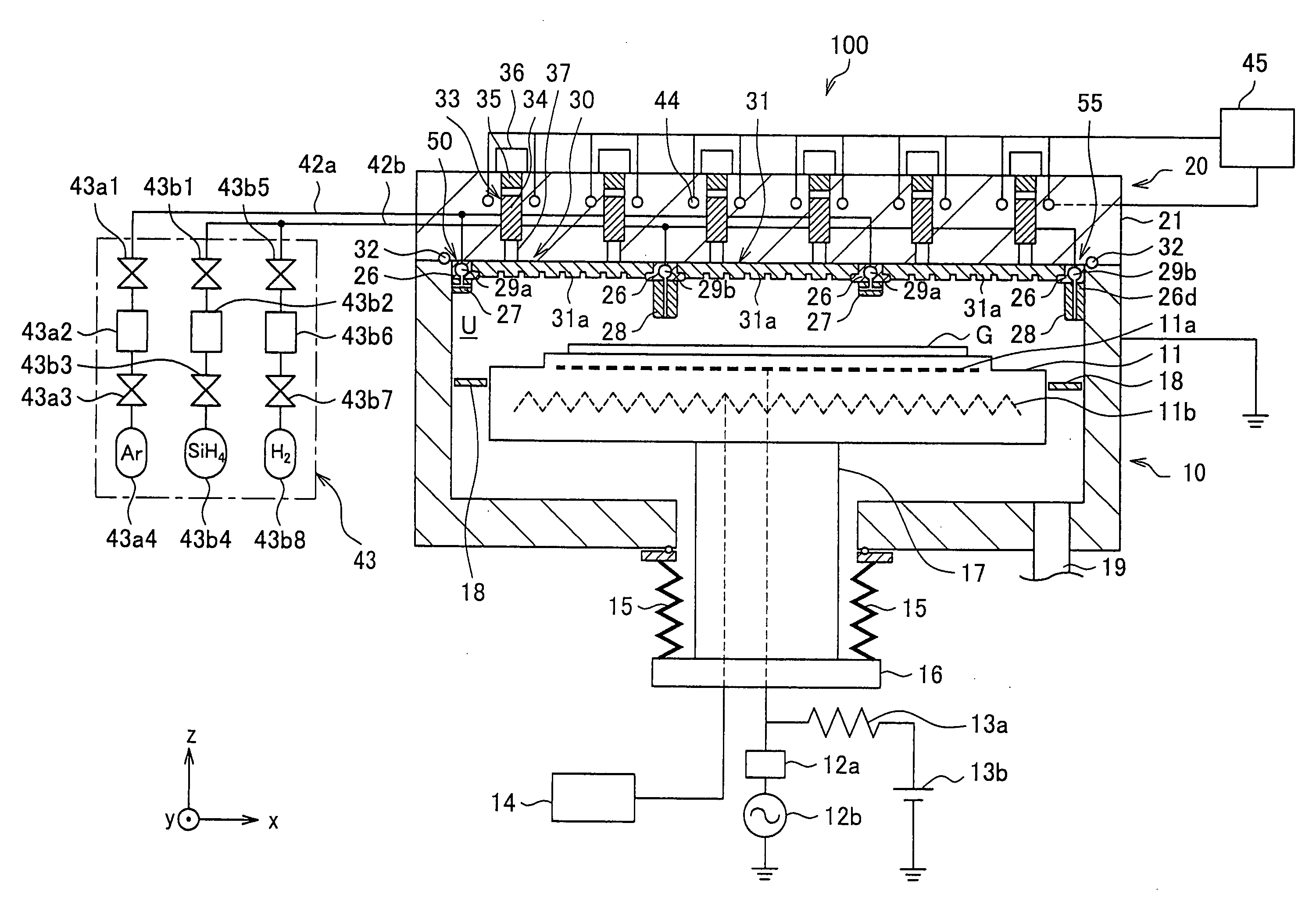
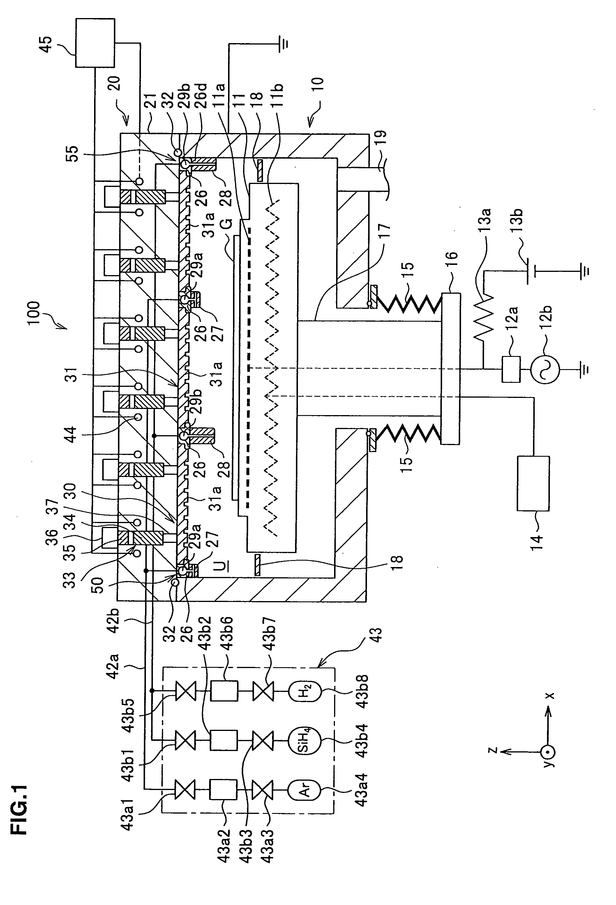
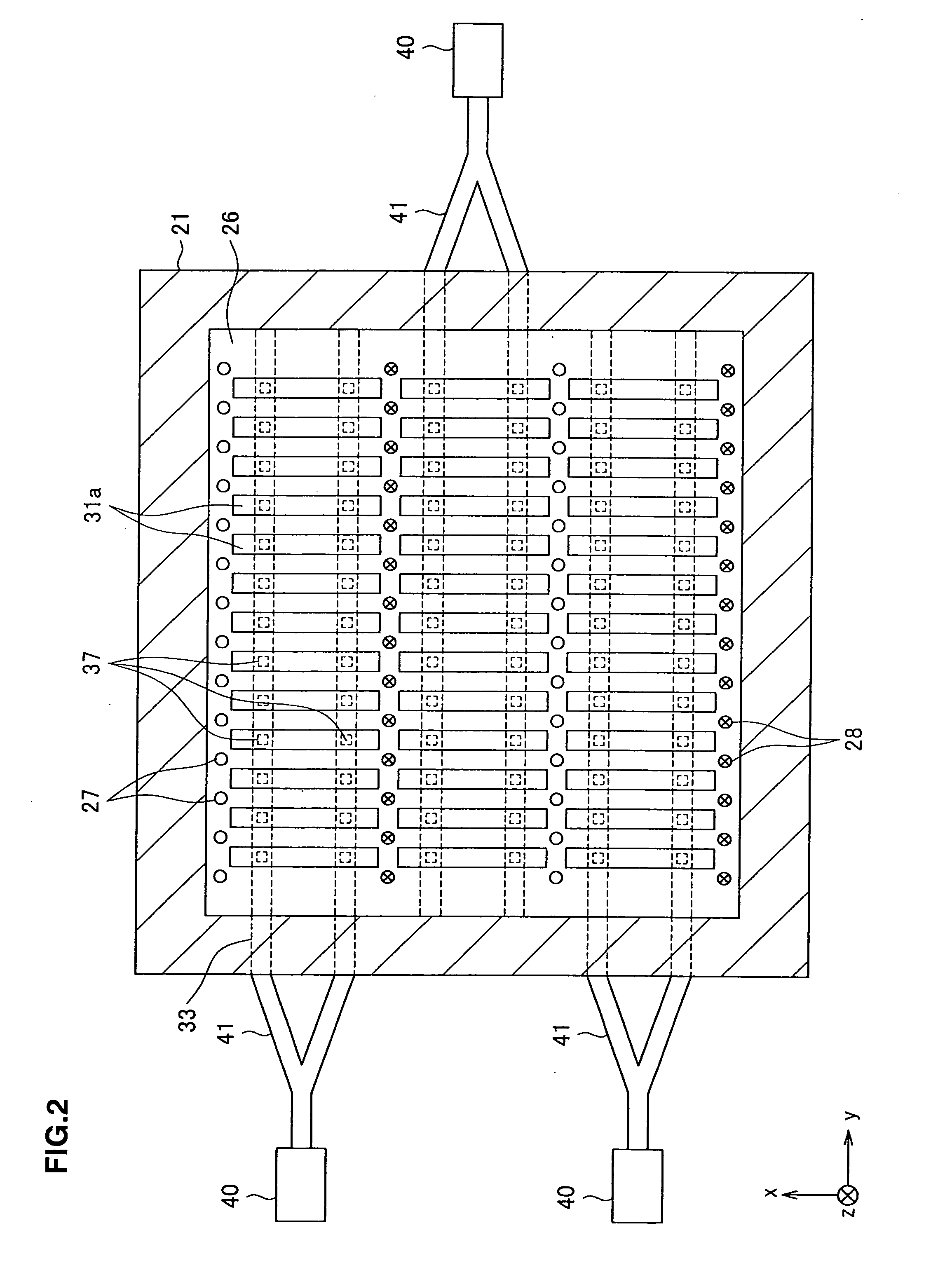
[0025]First, in reference to FIG. 1 presenting a sectional view of the microwave plasma processing apparatus achieved in an embodiment of the present invention, taken along the longitudinal direction (the direction perpendicular to the y-axis) and FIG. 2 presenting a view of the ceiling of the processing chamber, the structure adopted in the microwave processing apparatus is explained. It is to be note...


PUM

PropertyMeasurementUnit
lengthaaaaaaaaaa
pressureaaaaaaaaaa
widthaaaaaaaaaa

Abstract

At a frame 26 in a microwave plasma processing apparatus 100, numerous horizontal spray gas nozzles 27 formed therein injection holes A and numerous vertical gas nozzles 28 formed therein injection holes B are fixed. A first gas supply means 50 injects argon gas through the injection holes A into an area near each dielectric parts 31a. A second gas supply means 55 injects silane gas and hydrogen gas through the injection holes B into a position at which the gases do not become over-dissociated. The gases injected as described above are raised to plasma with a microwave transmitted through each dielectric parts 31a. Since the vertical gas nozzles 28 are mounted at positions at which they do not block the flow of plasma traveling toward a substrate G, ions and electrons do not collide with the vertical gas nozzles 28 readily.

Description

CROSS-REFERENCE TO RELATED APPLICATION[0001]This application is based upon and claims the benefit of priority from Japanese Patent Application No. 2006-10131, filed on Jan. 18, 2006, the entire content of which is incorporated herein by reference.BACKGROUND OF THE INVENTION[0002]1. Field of the Invention[0003]The present invention relates to a plasma processing apparatus and a plasma processing method for plasma processing a workpiece by generating plasma. More specifically, the present invention relates to how a processing gas to be used to generate plasma may be supplied.[0004]2. Description of the Related Art[0005]There are plasma processing apparatuses proposed in the related art that adopt a dual gas supply system whereby a plurality of different types of processing gases are supplied through two gas supply mechanisms (e.g., gas shower heads) separately disposed at an upper level and a lower level inside the processing container. In such a plasma processing apparatus, the upper...

Claims


Application Information

Patent Timeline
Patent Type & Authority Applications(United States)
IPC IPC(8): C23F1/00H01L21/302H01L21/306C03C15/00B44C1/22
CPCH01J37/3244H01J37/32192H01J37/32229
Inventor HORIGUCHI, TAKAHIRO
Owner TOKYO ELECTRON LTD
Why Eureka
Try Eureka