Shaped biocompatible radiation shield and method for making same

a radiation shield and biocompatible technology, applied in the direction of radiation beam directing means, instruments, therapy, etc., can solve the problems of tissue disposed between the radiation source and the target being exposed to radiation, and achieve the effect of facilitating positioning and reducing low energy radiation

Inactive Publication Date: 2006-09-19
CARL ZEISS STIFTUNG DOING BUSINESS CARL ZEISS
View PDF16 Cites 132 Cited by
  • Summary
  • Abstract
  • Description
  • Claims
  • Application Information

AI Technical Summary

Benefits of technology

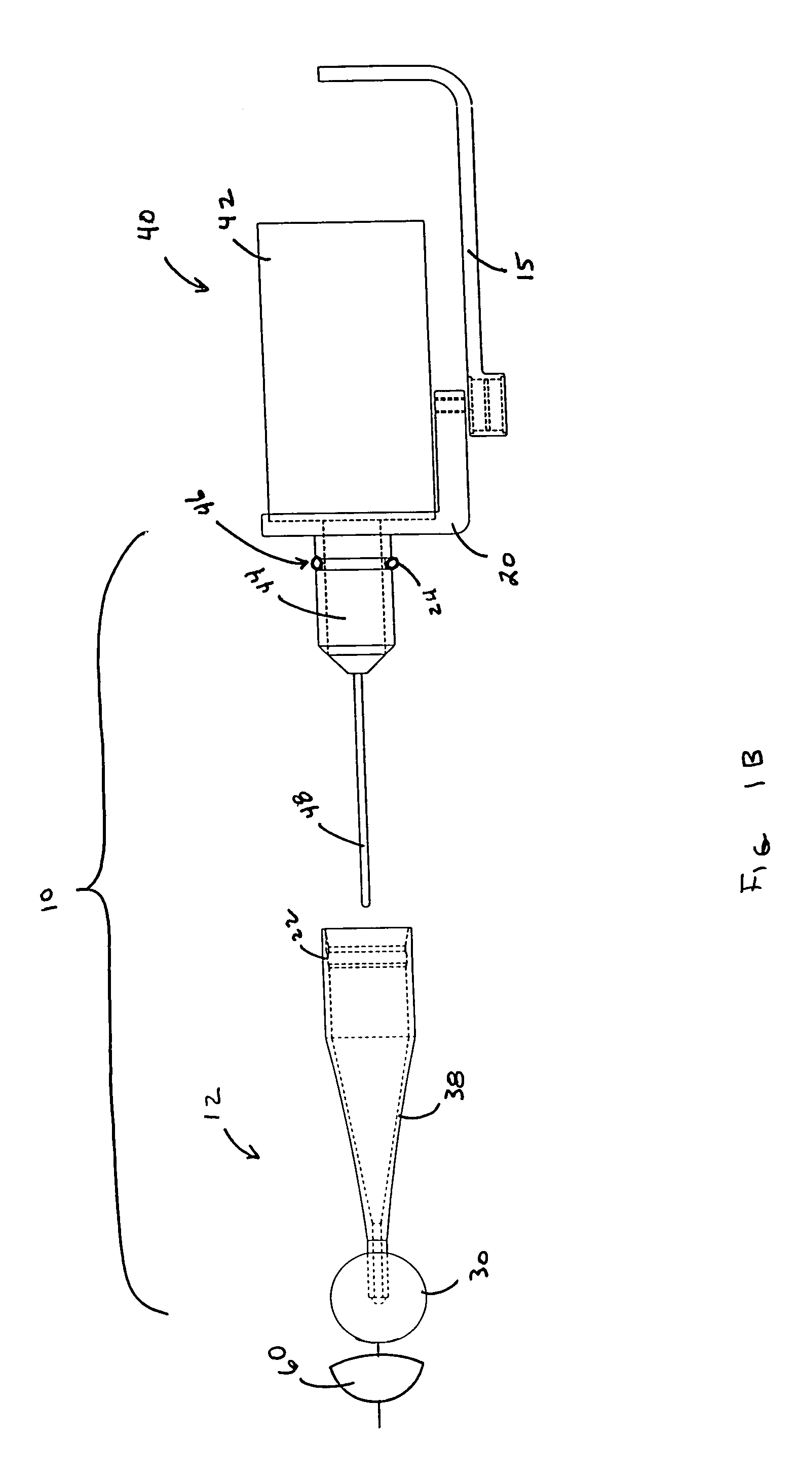
[0012]The present invention is directed to a biocompatible radiation shield for use with a radiation applicator system, which is mountable to a radiation source in order to apply a predefined dose of radiation to an area or volume. The radiation applicator system includes an applicator and adapter. The adapter couples the applicator to a radiation source. The applicator includes an applicator shank and an applicator head. The adapter engages the applicator shank at the shank'proximal end and thereby allows coupling of the applicator to the radiation source, when the adapter is coupled to the radiation source. At the opposite and distal end of the applicator shank is the applicator head, which is used for applying a predefined dose of radiation across a surface contour to treat a predefined volume of tissue surrounding a surgical site. Preferably, the applicator head and surface contour coincide such that the surface of the applicator head engages and/or supports the area or volume to be treated and applies a uniform dose of radiation over the area or volume to be treated.
[0013]The radiation shield is preferably formed to a predefined shape and size and adapted to be coupled to the applicator head in a predefined location in order to shield predefined portions of the treatment area or volume from radiation or to define the shape of the dose of radiation applied to the treatment area or volume. The biocompatible radiation shield is substantially thin and can be coupled to the surface of the applicator head, forming a thin shielding layer between the applicator head and the area or volume to be treated. The radiation head could also be integral with another material that is disposed, at least in part, over the applicator

Problems solved by technology

This treatment suffers from the disadvantage that tissue disposed b

Method used


Image

  • Shaped biocompatible radiation shield and method for making same
  • Shaped biocompatible radiation shield and method for making same
  • Shaped biocompatible radiation shield and method for making same

Examples


Embodiment Construction

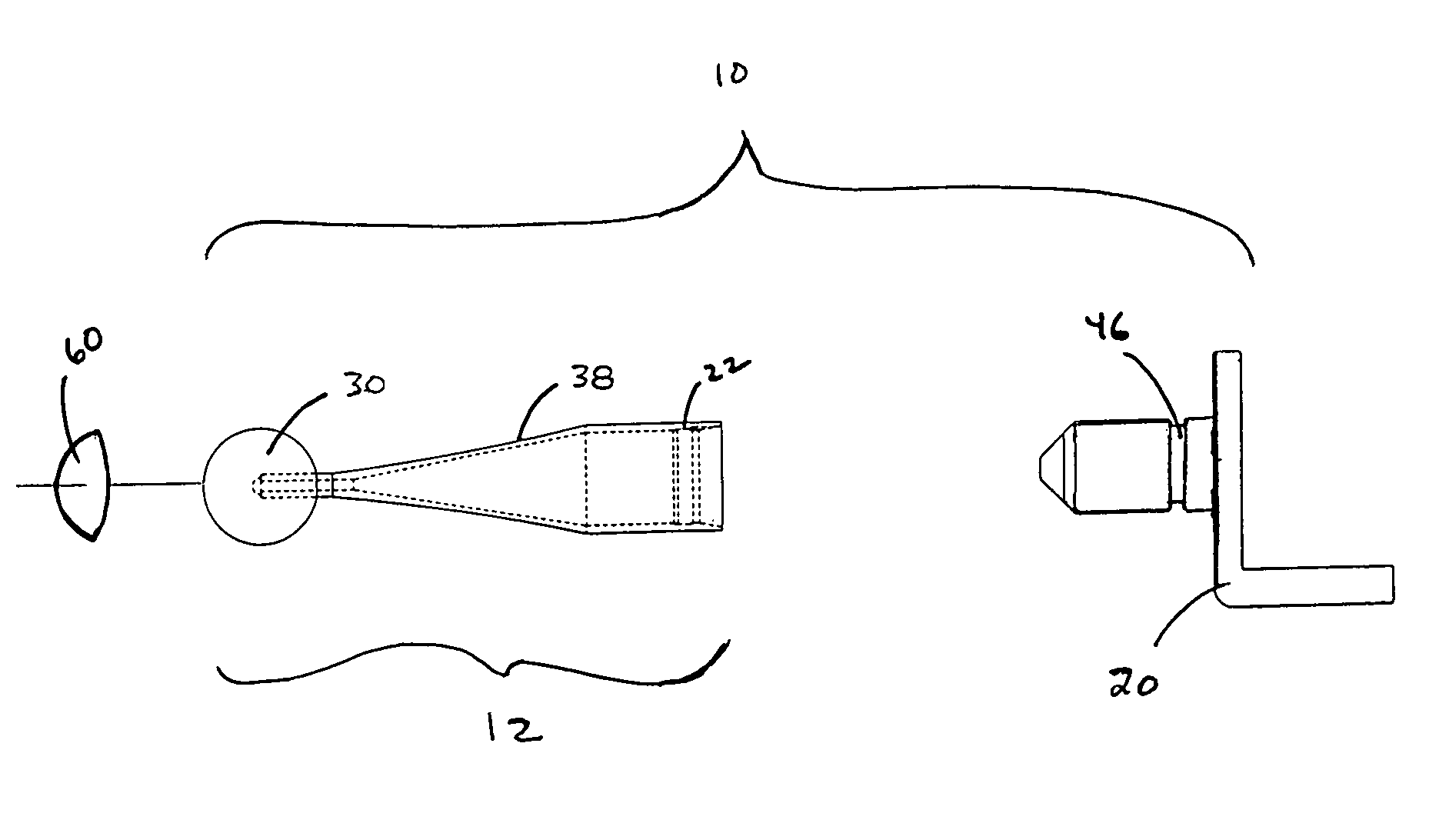
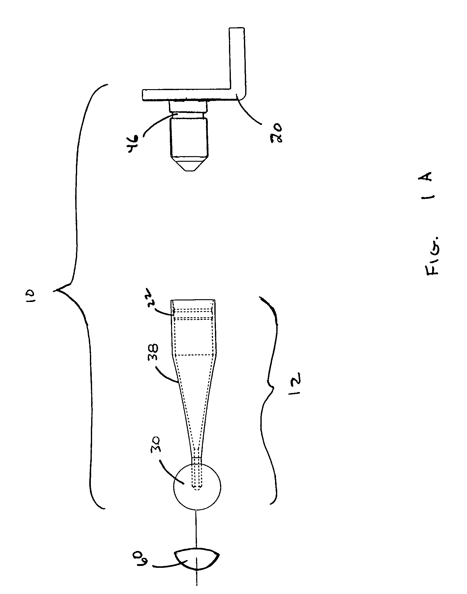
[0023]FIG. 1A shows an applicator system 10 and a biocompatible radiation shield 60 for applying a dose of radiation to an area to treat a volume of tissue. The applicator system 10 includes an applicator 12 and an adapter 20. Applicator 12 includes a shank 38 and a head 30, wherein head 30 is located at a distal end of shank 38. A proximal end of shank 38 removably engages with adapter 20 to form applicator system 10. Wherein adapter 20 is structured for attaching applicator system 10 to a radiation source (not shown). At the opposite and distal end of applicator shank 38, applicator head 30 is adapted for engaging and conforming a tissue cavity to a desired shape in order to permit the area or volume adjacent the tissue cavity to be treated with a predefined dose of radiation.

[0024]The biocompatible radiation shield 60 is fastened to the applicator head 30 in order to shield a portion of the treatment area or volume from the dose of radiation. The shape of the applicator head 30 c...


PUM


Abstract

A radiation applicator system is structured to be mounted to a radiation source for providing a predefined dose of radiation for treating a localized area or volume, such as the tissue surrounding the site of an excised tumor. The applicator system includes an applicator and an adapter. The adapter is formed for fixedly securing the applicator to a radiation source, such as a radiosurgery system which produces a predefined radiation dose profile with respect to a predefined location along the radiation producing probe. The applicator includes a shank and an applicator head, wherein the head is located at a distal end of the applicator shank. A proximate end of the applicator shank couples to the adapter. A distal end of the shank includes the applicator head, which is adapted for engaging and/or supporting the area or volume to be treated with a predefined does of radiation. The applicator can include a low energy radiation filter inside of the applicator head to reduce undesirable low energy radiation emissions. A biocompatible radiation shield may be coupled to the outer surface of the applicator head to block radiation emitted from a portion of the radiation probe, in order to shield an adjacent location or vital organ from any undesired radiation exposure. A plurality of applicators having applicator heads and radiation shields of different sizes and shapes can be provided to accommodate treatment sites of various sizes and shapes.

Description

REFERENCE TO RELATED APPLICATIONS[0001]This application is related to U.S. patent application Ser. No. 09 / 502,759, filed Feb. 11, 2000, now U.S. Pat. No. 6,421,416 and U.S. patent application Ser. No. 09 / 502,273, filed Feb. 11, 2000, now U.S. Pat. No. 6,301,326.STATEMENT REGARDING FEDERALLY SPONSORED RESEARCH[0002]Not ApplicableREFERENCE TO MICROFICHE APPENDIX[0003]Not ApplicableBACKGROUND OF THE INVENTION[0004]This invention relates to a miniaturized, programmable radiation source for use in delivering substantially constant or intermittent levels of x-rays to a specified region and, more particularly, to an apparatus for delivering a controlled dose of radiation to a localized volume of tissue, such as a volume of tissue of the human body.[0005]In the field of medicine, radiation is used for diagnostic, therapeutic and palliative treatment of patients. The conventional medical radiation sources used for these treatments include large fixed position machines such as linear accelera...

Claims


Application Information

Patent Timeline
IPC IPC(8): G02B5/00A61B6/08A61N5/10
CPCA61N5/1015A61N5/1001A61B6/08A61N2005/1094
Inventor SLISKI, ALAN P.HARTE, KENNETH J.
Owner CARL ZEISS STIFTUNG DOING BUSINESS CARL ZEISS
Why Eureka
Try Eureka