Device for, in particular bistatic radar applications

a radar and bistatic technology, applied in the direction of measuring devices, instruments, using reradiation, etc., can solve the problems of inability to synchronize, no longer unique velocity determination, and only increasing energy

Inactive Publication Date: 2006-09-19
ROBERT BOSCH GMBH
View PDF3 Cites 24 Cited by
  • Summary
  • Abstract
  • Description
  • Claims
  • Application Information

AI Technical Summary

Benefits of technology

[0014]The present invention renders possible a cross-echo detection and distance measurement when working with bistatic pulsed radars, i.e., with spatially separate transmitting and receiving antennas and carrier frequency oscillators, it being possible for both carrier frequency oscillators of any one transmitter / receiver pair, in contrast to conventional bistatic systems, to be run in asynchronous operation, i.e., they do not necessarily have to be frequency-synchronized or phase-synchronized.
[0017]It is thus possible to implement a bistatic pulsed radar in the low cost range as well, using low transmitting power to measure small cross-echo distances (given small baselines), and components that are not of high quality. In pulsed-radar arrays, it may be used to simultaneously measure direct and cross-echo distances. The additional cross-echo distances increase the spatial sampling of the sensor surroundings, may be used for classifying object contours, and enhance the redundancy of the sensor information.
[0018]The time-synchronous pulse modulation of the carriers of adjacent sensors and mixing of transmitted and received signals result in “image signals” having frequency components below half of the pulse repetition frequency PRF. These are referred to in the following as “cross-echo Dopplers”. The mid-frequency of such a cross-echo Doppler may be adjusted via the pulse repetition frequency PRF. The power of the cross-echo Doppler supplies a continuous low-frequency signal, thereby rendering possible cross-echo detection and distance measuring.

Problems solved by technology

However, if velocities occur that can result in fD being greater than PRF / 2, the velocity determination is no longer unique.
However, to achieve the desired coherence, considerable outlay must be expended to synchronize the phases (e.g., use of lock-pulse methods or digital detectors of the transmission phase).
Given a predefined pulse repetition frequency, limited peak power output of the transmitter, and limited permissible integration time, the energy can only be still increased by prolonging the pulse duration.

Method used


Image

  • Device for, in particular bistatic radar applications
  • Device for, in particular bistatic radar applications
  • Device for, in particular bistatic radar applications

Examples


Embodiment Construction

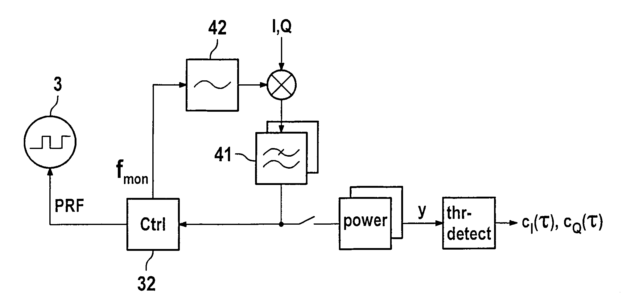
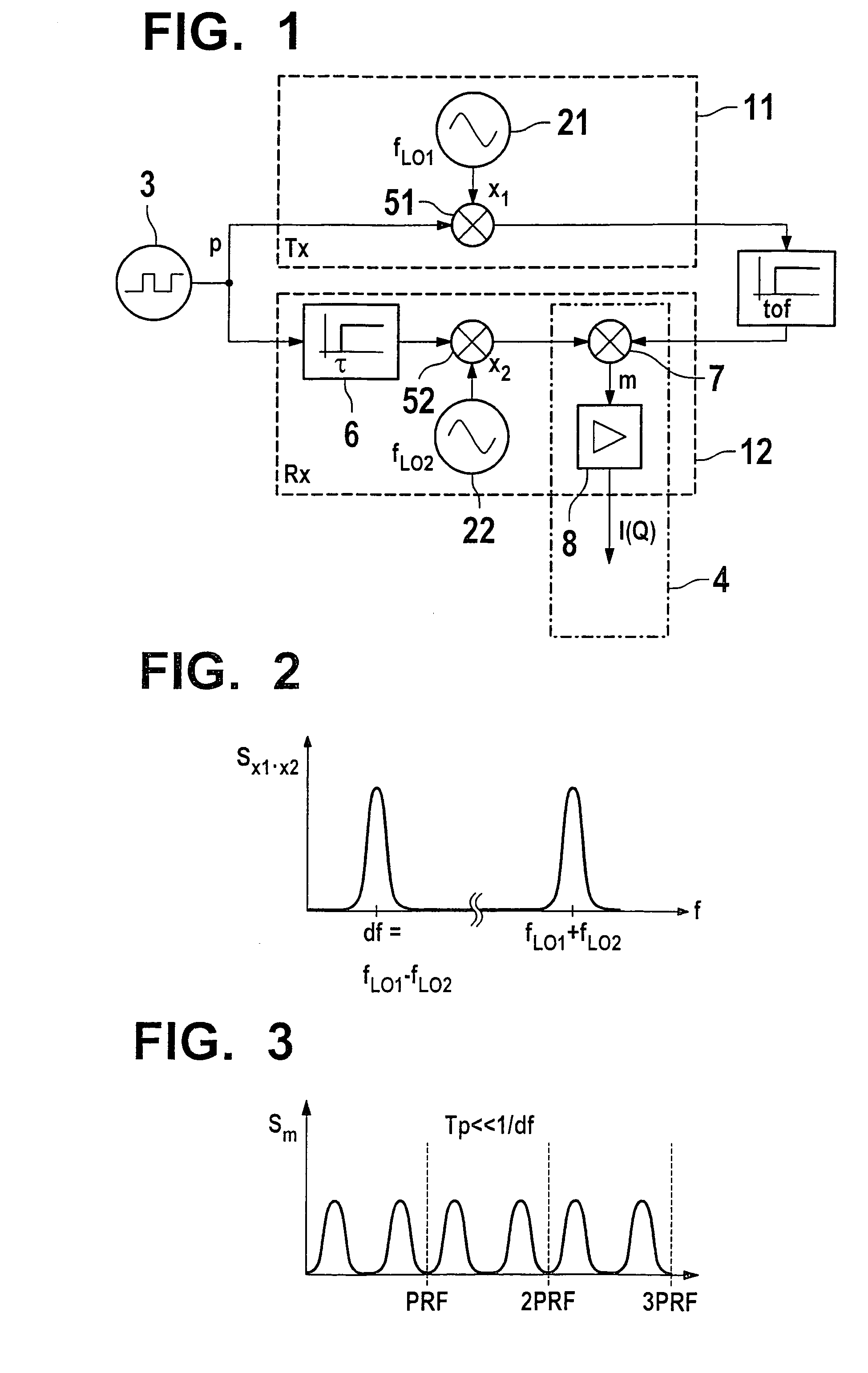
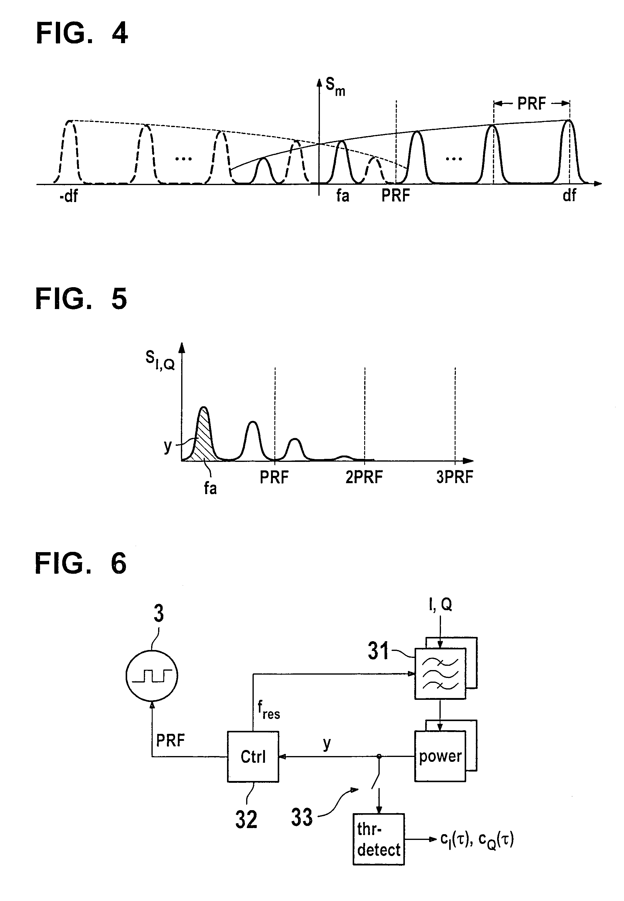
[0029]FIG. 1 shows two pulsed-radar sensors 11, 12, of which top sensor 11 functions as transmitter (Tx), bottom sensor 12 functions as receiver (Rx). Using their respective carrier-frequency oscillators 21, 22, the sensors generate carrier signals x1 and x2 having individual carrier frequencies fL01 and fL02. These carrier signals are modulated by the same pulsed source 3 using the 0–1 pulse sequence p, i.e., via modulators 51, 52, pulses are impressed on the output signals of the carrier-frequency oscillators. A separate pulsed signal source 3 may also be assigned to each of sensors 11, 12. However, this requires synchronizing these pulsed signal sources among one another. This may be accomplished either by using a connecting lead, or otherwise by recovering the transmitter pulse repetition frequency from the received signal and compensating for the phase offset. The phase offset may be determined by utilizing redundancy, since, due to the reversibility of signal paths (S11S12), t...


PUM


Abstract

In a device for bistatic radar applications, at least two spaced-apart radar sensors having separate carrier-frequency oscillators are provided, which do not require phase synchronization. The pulse modulation is carried out time-synchronously for all transmitter and receiver pairs. The cross-echo signals can be analyzed in an analyzing unit, in which a mixing of the transmitted and received signals takes place.

Description

FIELD OF THE INVENTION[0001]The present invention is directed to a device for bistatic radar applications.BACKGROUND INFORMATION[0002]The fundamental operation of pulsed radars for measuring the distance and velocity of objects had already been described in 1938 by Col. William Blair of the U.S. Signal Corps. When a microwave carrier undergoes pulse modulation, a signal of a defined pulse duration Tp is periodically transmitted at the pulse repetition frequency PRF. The signal reflected off of an object is attenuated in the receiver to the baseband range. By analyzing the baseband signal, the signal propagation time T and possibly the signal Doppler shift fD are determined. From the propagation time T, the object-sensor slant distance R is derived, ultimately based on the speed of light c, from the relationship R=c·T / 2, and the object velocity v is determined, with the carrier frequency being fC, from the relationship v=c / 2·fD / fC.[0003]Conventional pulsed radar systems use the follo...

Claims


Application Information

Patent Timeline
Patent Type & Authority Patents(United States)
IPC IPC(8): G01S13/10G01S13/12G01S13/58G01S13/00G01S13/46G01S13/22G01S13/87
CPCG01S13/003G01S13/87G01S13/582G01S13/22
Inventor KLINNERT, ROLANDZOTT, CHRISTIAN
Owner ROBERT BOSCH GMBH
Why Eureka
Try Eureka