Oversampled clip-shaping

a clip-shaping and oversampling technology, applied in the field of transmission systems, can solve the problems of high power consumption, high precision and high power consumption of components, and increase the bit error rate of transmission, so as to reduce or eliminate the effect of reducing or eliminating the upstream ber impa

Active Publication Date: 2006-09-19
TEXAS INSTR INC
View PDF7 Cites 14 Cited by
  • Summary
  • Abstract
  • Description
  • Claims
  • Application Information

AI Technical Summary

Benefits of technology

[0006]The present invention achieves technical advantages as an apparatus, system and method of peak-to-average reduction of an oversampled signal for a digital communication system. Peak detection and width measurement are advantageously combined in which a peak portion of an input signal that exceeds a predetermined threshold is detected and a width of the peak portion is determined. The peak detection and width measurement are further combined with a novel variable width shape generation methodology in which a variable width shaping response is applied to the peak portion responsive to the peak portion width. Additionally, a novel receiver technique can be included to reduce or eliminate the upstream BER impact using downstream shaping.
[0007]In another embodiment, peak detection and width measurement are advantageously combined in which multiple peak portions of an input signal that exceed a predetermined threshold are detected and a width of each peak portion is determined. Further, a variable width shaping response is applied to the respective multiple peak portions. Additionally, a novel receiver technique can be include to reduce or eliminate the upstream BER impact using downstream shaping for the multiple peak portion approach.

Problems solved by technology

These type of transmission systems typically have a transmitted signal with a higher peak-to-average ratio (PAR) than single carrier transmission system, and thus generally require components with high precision and high power consumption.
Some current systems attempt to limit PAR levels by hard-clipping the transmitted signal, however, several problems can arise from current clipping techniques.
For example, in an effort to reduce a transmitted peak, split peaks can result which subsequently can cause peak growth and / or re-growth near the original peak.
Further, as a signal's peak width varies and as peaks occur closely together, PAR reduction becomes more difficult and can lead to bit errors which increases the bit error rate of transmissions.

Method used


Image

  • Oversampled clip-shaping
  • Oversampled clip-shaping
  • Oversampled clip-shaping

Examples


Embodiment Construction

[0022]The numerous innovative teachings of the present application will be described with particular reference to the presently preferred exemplary embodiments. However, it should be understood that this class of embodiments provides only a few examples of the many advantageous uses and innovative teachings herein. In general, statements made in the specification of the present application do not necessarily delimit any of the various claimed inventions. Moreover, some statements may apply to some inventive features, but not to others.

[0023]There are several issues which need to be considered when considering a time-domain approach such as clip-shaping. For example, the height, width, shape and separation of peaks are almost limitless. Additionally, the reduction of one peak, if not done properly, has the ability to create additional peaks and desired signal changes to realize PAR reduction need to be maintained through any subsequent filtering operations.

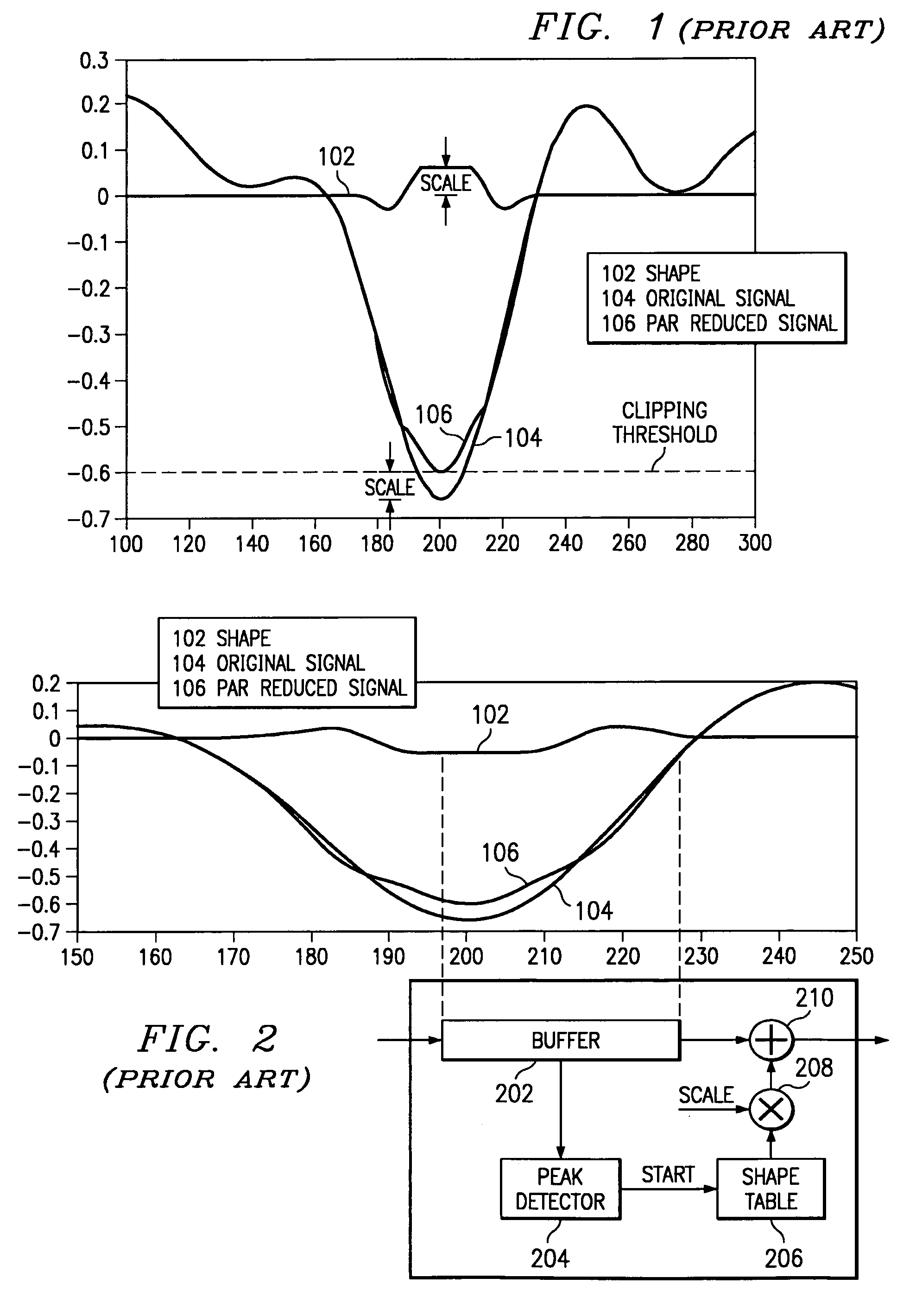
[0024]FIG. 1 illustrates a ...


PUM


Abstract

The present invention provides an apparatus, system and method of peak-to-average reduction of an oversampled signal for a digital communication system. Peak detection 504 and width measurement 504 are advantageously combined in which a peak portion or multiple peak portions of an input signal that exceeds a predetermined threshold is detected and a width of the peak portion is determined. The peak detection and width measurement are further combined with a novel variable width shape generation methodology 506 in which a variable width shaping response is applied 510 to the peak portion responsive to the peak portion width. Additionally, a novel receiver technique 1390 can be included to reduce or eliminate the upstream BER impact using downstream oversampled shaping.

Description

BACKGROUND OF THE INVENTION[0001]1. Technical Field of the Invention[0002]The present invention relates generally to transmission systems and, more particularly, to an apparatus, system and method for clip-shaping in such systems.[0003]2. Background of Related Art[0004]Transmission systems using multicarrier modulation are becoming increasingly important. An example of a transmission system using multicarrier modulation is an Asymmetric Digital Subscriber Line (ADSL). Some ADSL modems use DMT, a multi-carrier modulation technique, to achieve high bandwidth efficiency. An ADSL transceiver system generally includes a modem at a central station or office adapted to transmit information in a down-stream signal to a modem at a remote terminal and to receive information in an up-stream signal transmitted by the modem at the remote terminal. Modems generally include a transmitter section and a receiver section isolated by a hybrid. The up-stream and down-stream signals pass through a commo...

Claims


Application Information

Patent Timeline
Patent Type & Authority Patents(United States)
IPC IPC(8): H04B3/46H04L27/26
CPCH04L27/2624
Inventor MELSA, PETER J.
Owner TEXAS INSTR INC
Why Eureka
Try Eureka