Ultrasonic diagnostic device and image processing device

a diagnostic device and ultrasonic technology, applied in ultrasonic/sonic/infrasonic image/data processing, image enhancement, instruments, etc., can solve the problems of inability to perform a sufficiently accurate extraction of a contour of an object, complex operation, and the need for manual tracing to achieve such accurate sample points, reduce the operational load of doctors, and improve the quality of medical care

Active Publication Date: 2006-09-19
KONICA MINOLTA INC
View PDF18 Cites 56 Cited by
  • Summary
  • Abstract
  • Description
  • Claims
  • Application Information

AI Technical Summary

Benefits of technology

[0014]The present invention is made in view of the above problems. Accordingly, an object of the present invention is to provide an ultrasonic diagnostic device and an image processing device that are capable of extracting a contour of an object to be examined from an ultrasound image with high accuracy without requiring the operator to perform many operations.

Problems solved by technology

The above conventional techniques, however, have a drawback in that they require an operator to perform a number of operations and instructions, or they cannot perform a sufficiently accurate extraction of a contour of an object.
Secondly, the operator needs to set a starting point that is used for extracting the boundary.
The operator needs to perform this window setting while checking learning effects, and so this is an intricate operation.
A contour obtained under this method significantly varies according to which sample points are selected, and therefore setting such accurate sample points requires as much labor and time as is required to manually trace a contour.
In addition, when calculations are repeatedly performed on the same image data, this image processing device cannot always extract the same contour without the operator selecting exactly the same sample points each time even if he has set them by taking into the account the tremendous amount of care and precision that is required by the manual tracing.
This image displaying device, however, is susceptible to noise in an image because it extracts a contour by simply converting density information for an ultrasound image into a binary representation.
This may result in extracting an incorrect contour of tissue and a part that is subject to examination.

Method used


Image

  • Ultrasonic diagnostic device and image processing device
  • Ultrasonic diagnostic device and image processing device
  • Ultrasonic diagnostic device and image processing device

Examples


first embodiment

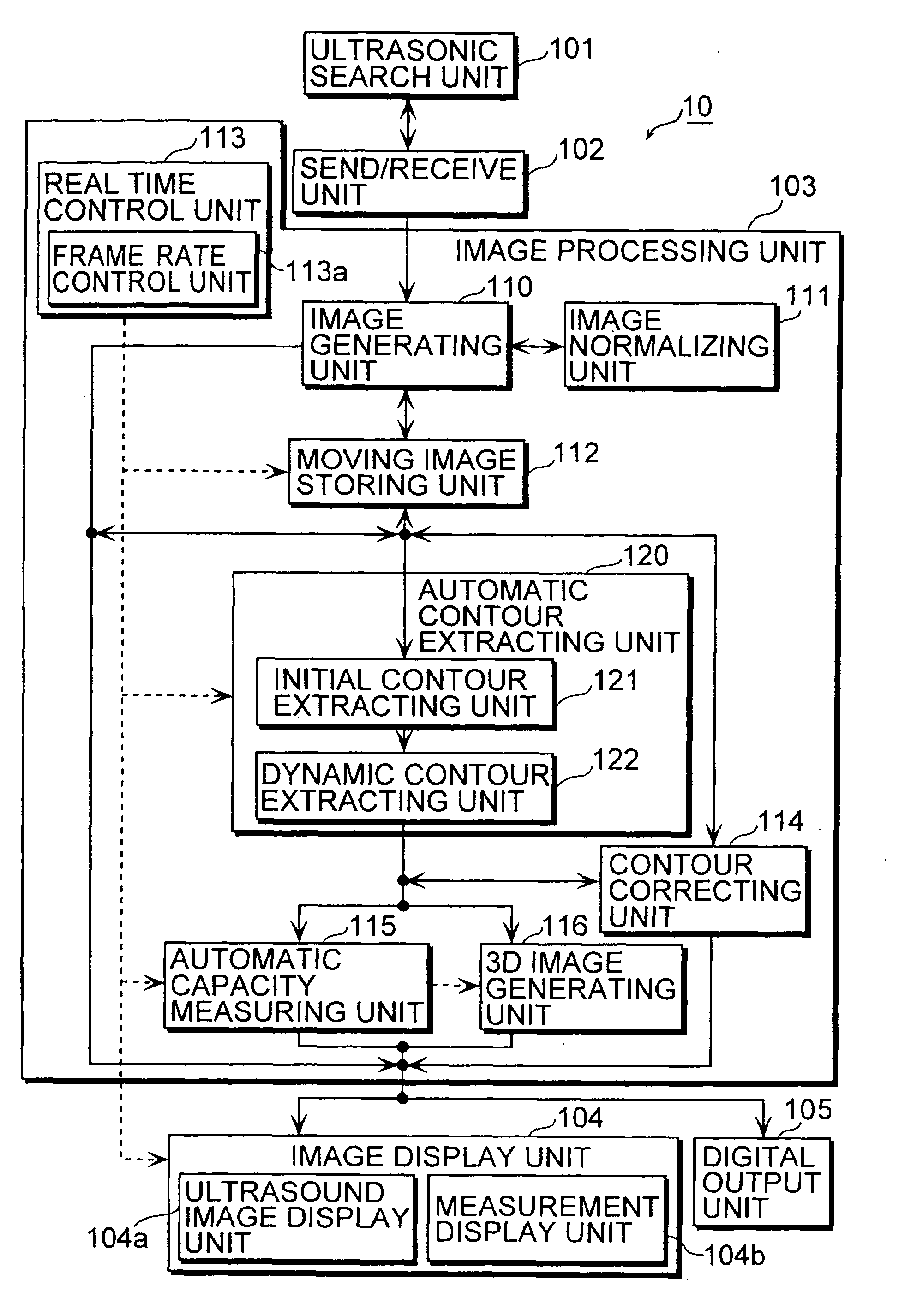
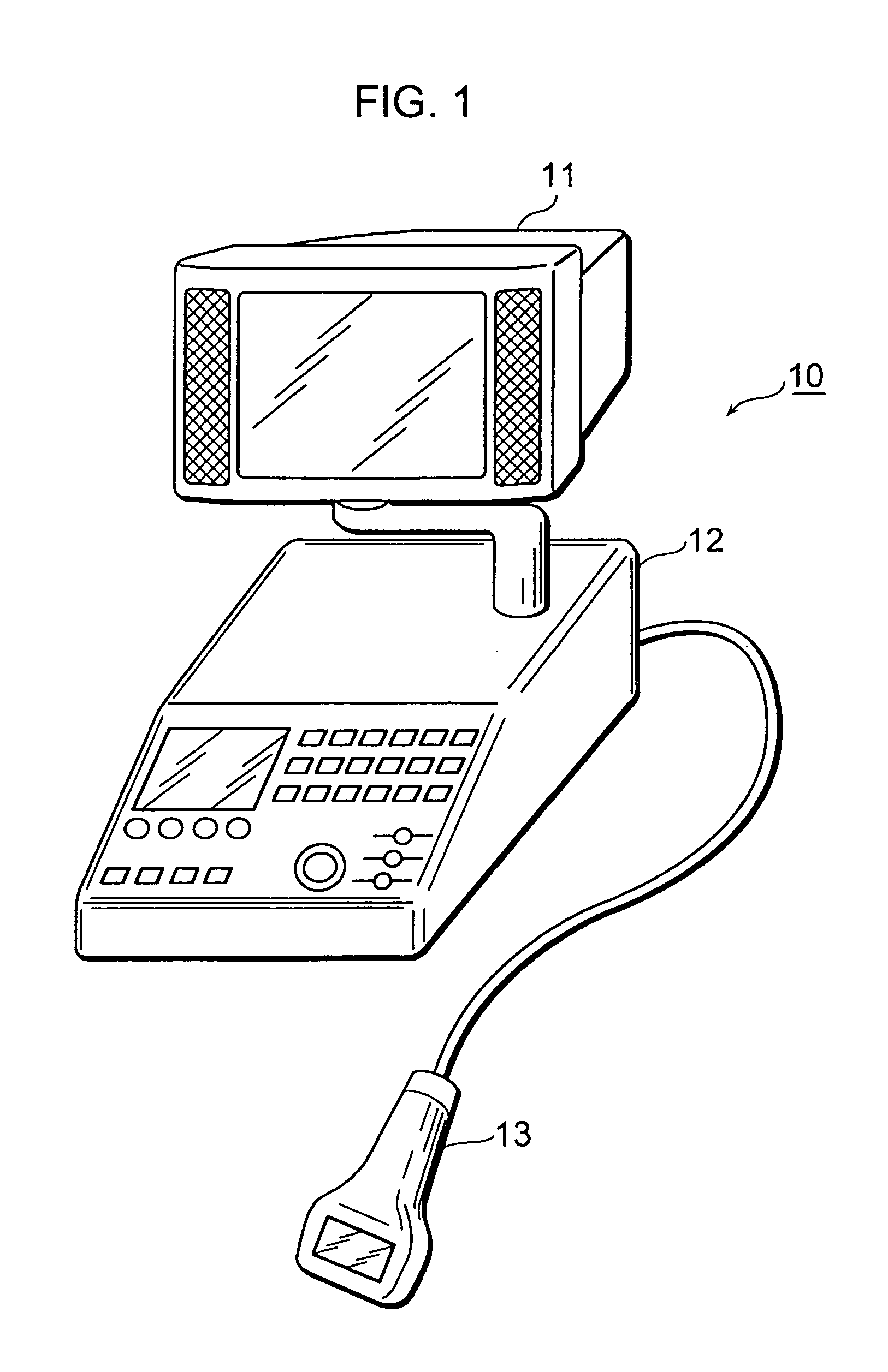
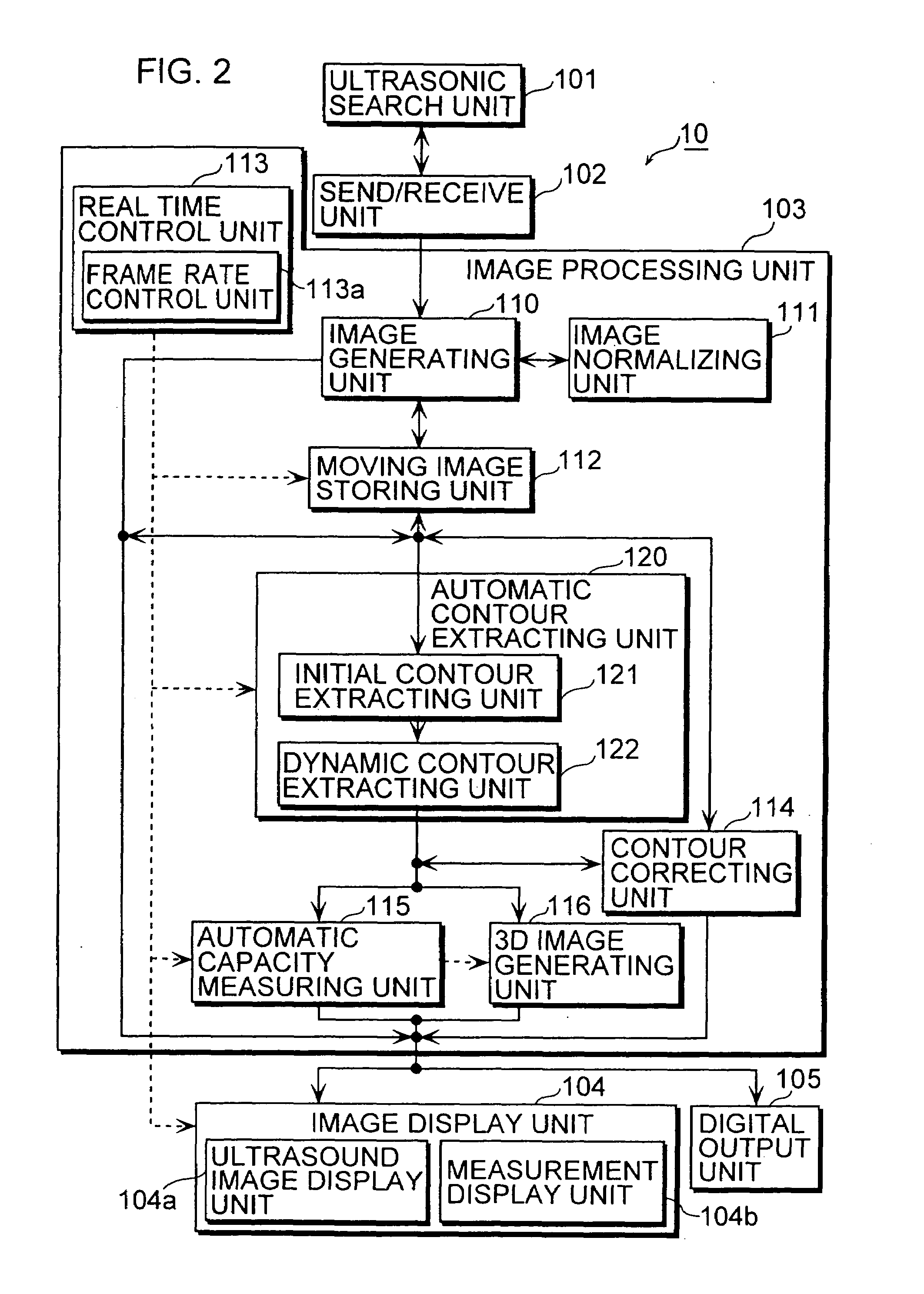
[0090]FIG. 1 shows an external view of a digital ultrasonic diagnostic device 10 according to the first embodiment of the present invention. This ultrasonic diagnostic device 10 not only generates ultrasound images of a fetus, an internal organ, a heart, and the like according to an echo method, but also automatically extracts a contour of an object of interest, such as cancerous tissue and an inner wall of a heart in a fetus and an internal organ. The ultrasonic diagnostic device 10 also calculates a capacity of this object and generates its 3D image in real time. The ultrasonic diagnostic device 10 includes, as its major hardware, a display apparatus 11, a main unit 12, and a probe 13.

[0091]The display apparatus 11 is a cathode-ray tube (CRT) or the like, whose front is covered by a transparent touch-screen panel. The display apparatus 11 displays the generated ultrasound image, contour, and measurement result in gray scale or color, and also receives instructions related to the g...

second embodiment

[0156]The following describes an ultrasonic diagnostic device 20 according to the second embodiment of the present invention. This ultrasonic diagnostic device 20 is the same as the diagnostic device 10 of the first embodiment in that the ultrasonic diagnostic device 20 automatically extracts a contour of an object from continuously generated ultrasound images and calculates a capacity of the object by using the extracted contour. The two ultrasonic diagnostic devices 10 and 20 differ, however, in that the ultrasonic diagnostic device 20 of the second embodiment uses a plurality of ultrasound images corresponding to different cross sections of the same object to calculate a capacity with high accuracy. The ultrasonic diagnostic device 20 also differs from the ultrasonic diagnostic device 10 in that the ultrasonic diagnostic device 20 displays synchronized images of different cross sections.

[0157]FIG. 13 is a block diagram showing a function configuration of the ultrasonic diagnostic...

example modifications

[0166]The following describes example modifications of the ultrasonic diagnostic devices 10 and 20 and their elements of the first and second embodiments.

[0167]An example modification relating to an image normalizing unit 211 that can replace the image normalizing unit 111 described in the above embodiments is described first.

[0168]FIG. 17A is a block diagram showing a detailed construction of the image normalizing unit 211. FIG. 17B illustrates contents of normalization performed by the normalizing unit 211 for an ultrasound image. FIG. 17B shows a transition of density distribution of the ultrasound image.

[0169]This image normalizing unit 211 is unique in that it performs different normalization for each object to be examined, and the image normalization unit 211 selects a conversion operation that is best suited for the object and performs the selected conversion operation to normalize an ultrasound image of the object. The image normalizing unit 211 includes a control judging un...


PUM


Abstract

An ultrasonic diagnostic device includes an automatic contour extracting unit that contains an initial contour extracting unit for roughly extracting an initial contour of an object to be examined from an ultrasound image by performing a predetermined operation (such as equalization, binarization, and degeneration) on the ultrasound image. The automatic contour extracting unit also contains a dynamic contour extracting unit for accurately extracting a final contour of the object by using the extracted initial contour as an initial value and by applying an active contour model, such as the SNAKES model, to the object within the ultrasound image.

Description

BACKGROUND OF THE INVENTION[0001](1) Field of the Invention[0002]The present invention relates to an ultrasonic diagnostic device and an image processing device, and particularly to a technique to extract a contour of an object that is subject to an examination from an image.(2) Description of Prior Art[0003]An ultrasonic diagnostic device receives an echo which is obtained when ultrasound emitted from an ultrasonic probe is partially reflected on reflection points and surfaces of tissue of an object of a living body that is subject to an examination. The ultrasonic diagnostic device then performs signal processing for the received echo, and generates an ultrasound image (an echo image) for the examined object. Since the ultrasonic diagnostic device generates a two-dimensional (2D) ultrasound image of an examined object of a soft part and the like without invasion, the ultrasonic device is widely used as a device which offers a high level of safety and is essential in fields such as...

Claims


Application Information

Patent Timeline
Patent Type & Authority Patents(United States)
IPC IPC(8): G06K9/00A61B8/08G06K9/64G06T1/00G06T5/00G06T7/60G16Z99/00
CPCG06F19/3437G06K9/6207G06T7/0083G06T7/602G06T7/0089G06F19/321G06F19/3406Y10S128/916G06T2207/10132G06T2207/30048Y10S128/915G06T7/12G06T7/149G06T7/62G16H40/63G16H50/50G16H30/40G16Z99/00G06V10/755A61B8/0883
Inventor YAMAUCHI, MASAKI
Owner KONICA MINOLTA INC
Why Eureka
Try Eureka