
Hybrid wireless optical and radio frequency communication link

Inactive Publication Date: 2006-09-19
SIGNIFY HLDG BV
View PDF151 Cites 86 Cited by
  • Summary
  • Abstract
  • Description
  • Claims
  • Application Information

AI Technical Summary

Benefits of technology

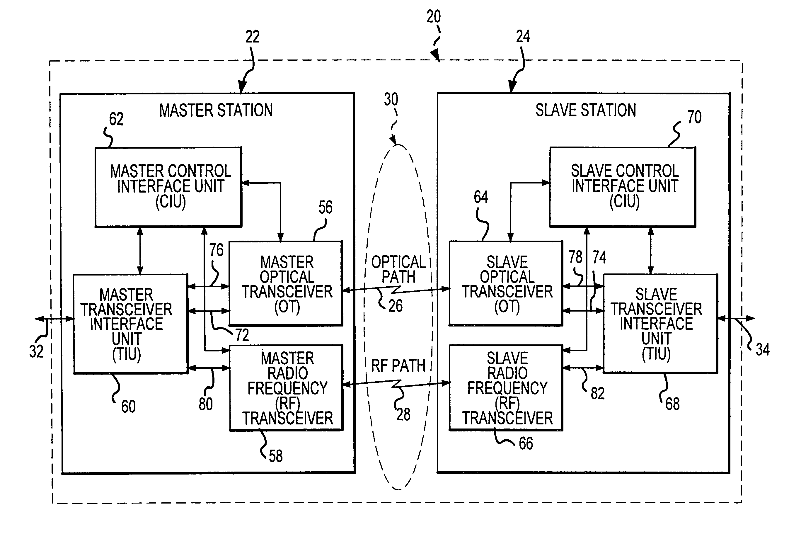
[0016]The present invention involves a hybrid wireless optical and radio frequency (RF) communication link or system. Optical transceivers at opposite ends of the link provide an optical path for the primary communication of the data, and RF transceivers primarily provide a communication path for control and status information between the optical and RF transceivers. Under atmospheric conditions that cause the optical communication of data to degrade severely or to fail altogether, data communication is automatically switched to the RF path. Although the overall data communication speed may be reduced when the data is transmitted over the RF path, a communication link is maintained under all conditions, rather than suspending data communication during atmospheric conditions which are adverse to optical data communication.
[0017]The presence of the RF path between the RF transceivers provides for highly reliable communication of the control and status information, regardless of whether the data is communicated over the optical or RF path. Thus, it is possible to pass control and status information to better control the optical transceivers and their optical signal transmissions, even when the optical link is not operating optimally due to deteriorated free-space atmospheric conditions.
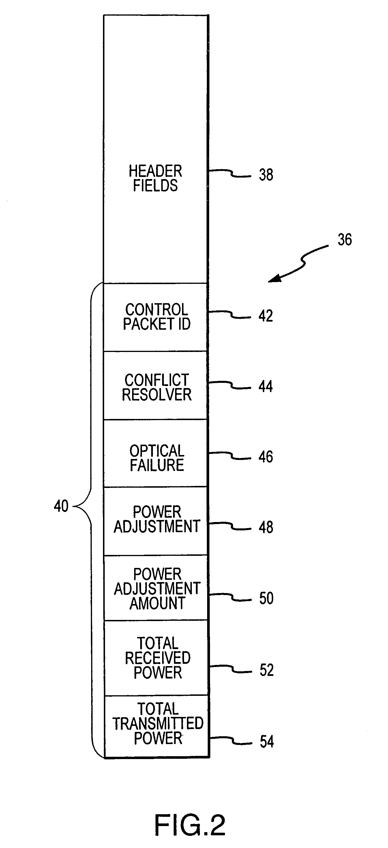
[0018]These and other improvements are achieved in an improved method for communicating data in a communication link extending across a terrestrial free-space region between two stations at ends of the link. The method involves communicating the data in an optical signal transmitted through a free-space optical path between the two stations, and communicating the data in a radio frequency (RF) signal transmitted through a free-space RF path between the two stations when the data is not transmitted in the optical signal through the optical path. The optical link is used to transmit the data whenever there is a benefit to using the optical path, and the RF link is used whenever atmospheric conditions in the optical path cause of the optical path to fail or degrade the transmission of the optical signals. A failure or degradation of the optical path is recognized by a failed reception of a transmitted optical signal or by the reception of an optical signal which has been degraded to the point that it is difficult to reliably distinguish the information contained in the optical signal. Control and status information is transferred between the optical transceivers over the RF path to communicate that the optical signal has failed or has degraded. Even while the RF link is transmitting the data, it is preferable to continue attempted transmission of optical signals between the communication points to determine when to reestablish the optical path for the transmission of data with the optical signals can be reliably communicated. The two stations preferably alternately generate and transmit the control and status information and send it to the other station. The control and status information includes information which indicates the amount by which one station should change its optical transmitting power according to the other station's assessment of the received power, thereby maintaining effective optical communication without oscillation of the power levels of the two stations.

Problems solved by technology

Although fiber optic links are capable of both high speed and high reliability, they have the disadvantage of requiring a physical installation of a fiber optic cable as the communication path or media between communication points.
In many situations, however, it is impractical, uneconomical or impossible to install physical cable media between communication points.
The optical beam is subject to degradation by smoke, dust, fog, rain, snow and any other particles in the atmosphere between the communication points.
At times, atmospheric conditions can so severely degrade quality of the light beam between the communication points that the free-space optics can fail to work altogether or that the communication rate is diminished to an unacceptable level.

Method used


Image

  • Hybrid wireless optical and radio frequency communication link
  • Hybrid wireless optical and radio frequency communication link
  • Hybrid wireless optical and radio frequency communication link

Examples


Embodiment Construction

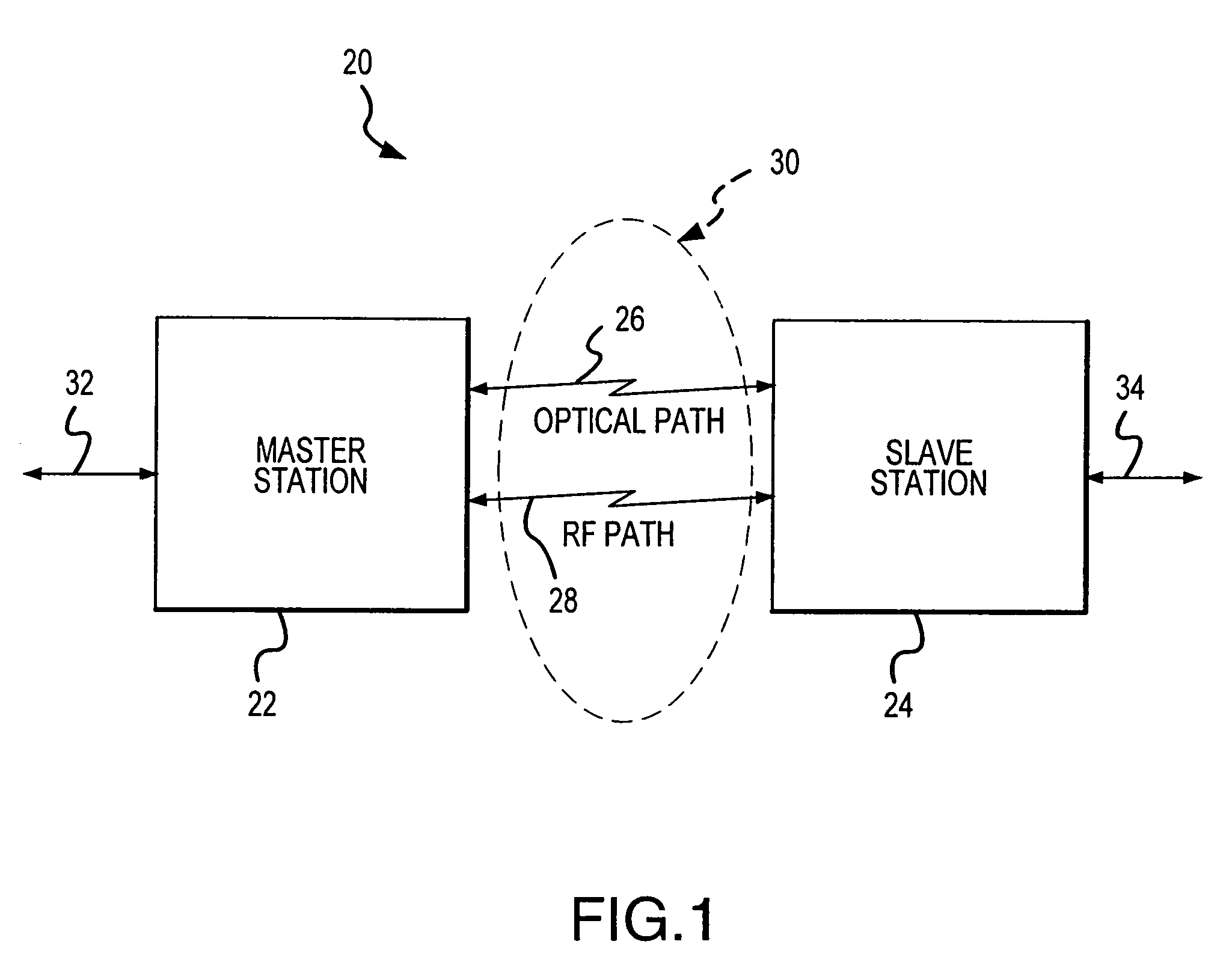
[0031]A hybrid wireless optical and radio frequency (RF) communication link (the hybrid link) 20 is shown in FIG. 1. The hybrid link 20 combines free-space optical communication technology (preferably laser systems which reach a communication speed of many gigabits per second) with high speed RF technology (preferably microwave) to achieve a wireless terrestrial hybrid laser / microwave communication link for the communication of data between two communication end-points of the hybrid link 20 at stations 22 and 24. The integration of these two wireless communication technologies (optical and RF) in the hybrid link 20 increases the statistical availability or reliability of long-distance (e.g. over 1–2 miles in distance), point-to-point wireless communication.

[0032]The hybrid link 20 preferably generally comprises a master hybrid communication station (master station) 22 and a slave hybrid communication station (slave station) 24. An optical signal, such as a laser beam, is projected i...


PUM


Abstract

A hybrid wireless optical and radio frequency (RF) communication link utilizes parallel free-space optical and RF paths for transmitting data and control and status information. The optical link provides the primary path for the data, and the RF link provides a concurrent or backup path for the network data, as well as a reliable and primary path for the control and status information. When atmospheric conditions degrade the optical link to the point at which optical data transmission fails, the hybrid communication link switches to the RF link to maintain availability of data communications. The switch may occur automatically, based on an assessment of the quality of the optical signal communicated through the optical path.

Description

CROSS-REFERENCE TO RELATED APPLICATIONS[0001]This application is a continuation of U.S. application Ser. No. 09 / 482,782, filed Jan. 13, 2000, now U.S. Pat. No. 6,763,195, the entire contents and disclosure of which is hereby incorporated herein by reference.[0002]This application is also related to the following application, which was made by one of the present inventors: Terrestrial Optical Communication Network of Integrated Fiber and Free-Space Links Which Requires No Electro-Optical Conversion Between Links, U.S. patent application Ser. No. 09 / 065,685, filed Apr. 24, 1998, now U.S. Pat. No. 6,239,888. The disclosure of this previous U.S. patent application is hereby incorporated by this reference.STATEMENT REGARDING FEDERALLY SPONSORED RESEARCH OR DEVELOPMENT[0003]This invention was made with Government support under contract DASG60-00-C-0055 awarded by U.S. Army Space and Missile Defense Command. The Government has certain rights in the invention.FIELD OF THE INVENTION[0004]Thi...

Claims


Application Information

Patent Timeline
IPC IPC(8): H04B10/00H04B1/74H04B10/02H04B10/10H04B10/118H04B10/22H04L69/40
CPCH04B10/114H04B10/1123H04B10/11
Inventor WILLEBRAND, HEINZACHOUR, MAHA
Owner SIGNIFY HLDG BV
Learn More