Magnetic resonance imaging for a plurality of selective regions set to object continuously moved

a selective region and magnetic resonance imaging technology, applied in the field of magnetic resonance imaging systems, can solve the problems of difficult speedy imaging, inability to acquire data efficiently, and non-standard mr imaging, so as to prevent or suppress artifacts, reduce data acquisition time, and reduce the effect of unnecessary signals

Inactive Publication Date: 2006-09-19
TOSHIBA MEDICAL SYST CORP
View PDF9 Cites 28 Cited by
  • Summary
  • Abstract
  • Description
  • Claims
  • Application Information

AI Technical Summary

Benefits of technology

[0013]The present invention has been made with due consideration to the foregoing drawbacks of conventional MR imaging that involves a continuous movement of an object. An object of the present invention is to make it possible that the MR imaging that involves a continuous movement of an object is able to employ imaging techniques and image-quality improving techniques, such as multi-slice imaging (including oblique imaging of multiple slices) and suppression of artifacts resulting from movement of an object, all of which are greatly effective in actual medical treatment.
[0017]These configurations are able to provide multi-slice imaging performed with an object moved continuously, which is helpful in actual medical treatment and is able to acquire data in improved efficiency. It is possible to obliquely set a slice-selective axis of multi-slices to a moving direction of an object. Hence, oblique imaging of multi-slices, which is modified from the multi-slice imaging, can be done. The imaging involving an object's continuous movement can therefore be enhanced in its functions, providing the system with improved convenience.
[0018]Further, even if an MRI system provides only a narrow imaging range as a “range that can be imaged (photographable range),” a region to be examined having a “wider range” than the narrow range can be imaged and a patient's throughput can be improved.
[0021]In addition, the magnetic resonance imaging system according to the present invention may be configured in such a manner that, in the foregoing configurations, echo data that have been acquired are subject to their phase correction. This prevents or suppresses artifacts from being caused due to phase shifts of signals in slices resulting from object's movements. It is also possible to include a preparation pulse in a pulse sequence used for scanning, which is helpful in preferable suppression of unnecessary signals and others.
[0022]Further, usable is a pulse sequence having a gradient pulse to be applied in the moving direction of the object, in which a phase compensation pulse for nulling a gradient moment of a first or second order is added to at least part of the gradient pulse. This addition of the phase compensation pulse is effective for compensating disturbances in signal phases resultant from object's movements, so that artifacts on account of the phase disturbances can be prevented or suppressed.
[0023]Still further, a pulse sequence can be configured by a train of pulses, which is formed on a fast spin echo method, of which gradient to be applied in a moving direction of an object meets, at least partly, a VIPS condition. This is effective for compensating disturbances in signal phases resultant from object's movements, so that artifacts on account of the phase disturbances can be prevented or suppressed. Additionally, a data acquisition time can be shortened.

Problems solved by technology

However, conventional MR imaging does not show the way of multi-slice imaging involving simultaneous selective-excitation of a plurality of slices.
Thus this leads to the problem that it is difficult to perform speedy imaging, because data cannot be acquired with efficiency.
Furthermore, conventional MR imaging that involves a continuous movement of an object does not provide practical ways to reduce artifacts, which will normally be caused due to constant-speed movements of the tabletop (that is, an object).

Method used


Image

  • Magnetic resonance imaging for a plurality of selective regions set to object continuously moved
  • Magnetic resonance imaging for a plurality of selective regions set to object continuously moved
  • Magnetic resonance imaging for a plurality of selective regions set to object continuously moved

Examples


first embodiment

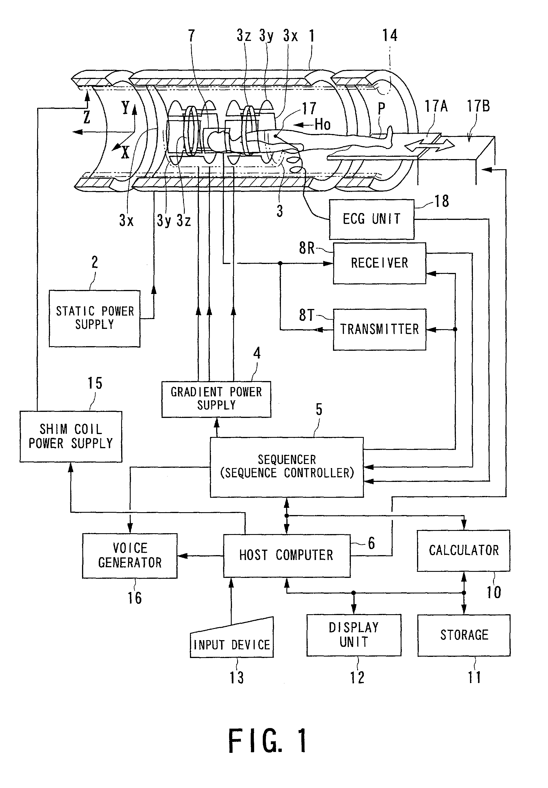
[0035]A first embodiment of the present invention will now be described. FIG. 1 shows an outlined configuration of an MRI (magnetic resonance imaging) system used in common in the following various embodiments.

[0036]The MRI system comprises a patient couch portion on which an object (patient) P lies down, static magnetic field generating components for generating a static magnetic field, magnetic field gradient generating components used for appending positional information to the static magnetic field, transmitting / receiving components for transmitting and receiving radio-frequency signals, control and arithmetic operation components responsible for both control of the whole system and image reconstruction, and electrocardiographing components for acquiring an ECG signal indicative of cardiac temporal phases of the object P.

[0037]The static magnetic field generating components include a magnet 1 formed into, for example, a superconducting type, and a static power supply 2 for suppl...

second embodiment

[0079]Referring to FIGS. 5 and 6, a magnetic resonance imaging system according to a second embodiment of the present invention will now be described. The hardware of this system is configured in the same way as that in the first embodiment.

[0080]In the foregoing first embodiment, adopted was the configuration in which the moving direction of an object agrees with the slice selecting direction. Instead, the present second embodiment provides an imaging technique called oblique imaging (scan) in which both of the above directions are different from each other. In practical diagnosis, the oblique imaging is performed, for example, in such a manner that a section to be imaged is set along a direction of the OM line of an object (patient).

[0081]The oblique imaging according to the present embodiment adopts scanning conditions determined to adjust the carrier frequency for selective excitation in compliance with the geometrical relationship between a moving direction of a patient P and a...


PUM


Abstract

MRI echo data is acquired by performing selective-excitation on regions composed of multi-slices of an object, while the object is moved continuously. The positions of the multi-slices are moved within a predetermined imaging range fixedly determined by an MRI system, according to object movement. This allows positions of the multi-slices to be changed in compliance with the moved object, so that the multi-slices positionally track with the object within the imaging range. Accordingly, a multi-slice imaging technique can be provided, which is executable during even continuous movement of the object.

Description

BACKGROUND OF THE INVENTION[0001]1. Technical Field[0002]The present invention relates to a magnetic resonance imaging (MRI) system for medical use, and in particular, to a magnetic resonance imaging system capable of imaging a plurality of selective regions, such as multi-slice regions, while an object to be imaged is continuously moved in a certain direction.[0003]2. Related Art[0004]In general, magnetic resonance imaging (MRI) can be defined as the imaging technique that magnetically excites nuclear spins of an object placed in a static magnetic field with a radio-frequency signal at a Larmor frequency and reconstructs an image from MR signals generated due to the excitation.[0005]Recently, in the field of the magnetic resonance imaging, there has been proposed a technique for imaging an object laid on a tabletop moved continuously in its longitudinal direction, in order to obtain an image whose field of view is wider than a system's own fixed imaging range. For instance, the “im...

Claims


Application Information

Patent Timeline
Patent Type & Authority Patents(United States)
IPC IPC(8): A61B5/05A61B5/00A61B5/055A61B6/00G01R33/48G01R33/54G01R33/563G01R33/565G01R33/567
CPCA61B5/055A61B6/469G01R33/4835G01R33/4833A61B6/541G01R33/56509G01R33/563A61B5/704
Inventor MACHIDA, YOSHIO
Owner TOSHIBA MEDICAL SYST CORP
Why Eureka
Try Eureka