Communication method and arrangement

a communication method and communication arrangement technology, applied in the field of automobility safety, intelligent highway safety system, accident elimination, collision avoidance, etc., can solve the problems of author (unnecessarily) complicating matters, insufficient rtzfTM system, interference from toll collection system, etc., to achieve the effect of avoiding accidents at intersections

Inactive Publication Date: 2006-09-19
AMERICAN VEHICULAR SCI
View PDF26 Cites 198 Cited by
  • Summary
  • Abstract
  • Description
  • Claims
  • Application Information

AI Technical Summary

Benefits of technology

[0089]4. To provide a system that substantially reduces the incidence of single vehicle accidents caused by the vehicle inappropriately leaving the roadway at high speed.
[0110]Outputs from multiple sensors as described above are used in onboard vehicle neural network and neural-fuzzy system computing algorithms to derive optimum vehicle warning and control signals designed to avoid vehicle collisions with other vehicles or with other objects or hazards that may be present on given roadways. In a preferred embodiment, neural fuzzy control algorithms are used to develop coordinated braking, acceleration and steering control signals to control individual vehicles, or the individual wheels of such vehicles, in an optimal manner to avoid or minimize the effects of potential collisions. Video, radar, laser radar, terahertz radar and GPS position and trajectory information are made available to each individual vehicle describing the movement of that vehicle and other vehicles in the immediate vicinity of that vehicle.

Problems solved by technology

This is unnecessary and the communications can be general since the amount of information that is unique to one vehicle is small.
However, the author (unnecessarily) complicates matters by using push technology which isn't absolutely necessary and with the belief that the Internet connection to a particular vehicle to allow all vehicles to communicate, would have to be stopped which, of course, is not the case.
DSRC could be used for inter-vehicle communications, however, its range according to the ITS proposal to the Federal Government would be limited to about 90 meters although there have been recent proposals to extend this to about 1000 meters.
Also, there may be a problem with interference from toll collection systems, etc.
This would not be sufficient for the RtZF™ system.
Fifty meters amounts to about one second, which would be insufficient time for the passing vehicle to complete the passing and return to the safe lane.
This, however, may interfere with other uses of DSRC such as automatic toll taking, etc., thus DSRC may not be the optimum communication system for communication between vehicles.
“Automotive suppliers cannot sell infrastructure-dependent systems to their customers until the very large majority of the infrastructure is suitable equipped.”
Additionally, no prior art system is believed to have successfully used the GPS navigational system, or an augmented DGPS to locate a vehicle on a roadway with sufficient accuracy that that information can be used to prevent the equipped vehicle from leaving the roadway or striking another similarly equipped vehicle.
Prior art systems in addition to being poor at locating potential hazards on the roadway, have not been able to ascertain whether they are in fact on the roadway or off on the side, whether they are threatening vehicles, static signs, overpasses etc.
In fact, no credible attempt to date has been made to identify or categorize objects which may impact the subject vehicle.
“Out-of-position” as used for an occupant will generally mean that the occupant, either the driver or a passenger, is sufficiently close to an occupant protection apparatus (airbag) prior to deployment that he or she is likely to be more seriously injured by the deployment event itself than by the accident.
It may also mean that the occupant is not positioned appropriately in order to attain the beneficial, restraining effects of the deployment of the airbag.

Method used


Image

  • Communication method and arrangement
  • Communication method and arrangement
  • Communication method and arrangement

Examples


Embodiment Construction

1. Vehicle Collision Warning and Control

[0139]According to U.S. Pat. No. 05,506,584 the stated goals of the US DOT IVHS system are:[0140]improving the safety of surface transportation[0141]increasing the capacity and operational efficiency of the surface transportation system[0142]enhancing personal mobility and the convenience and comfort of the surface transportation system[0143]reducing the environmental and energy impacts of the surface transportation system

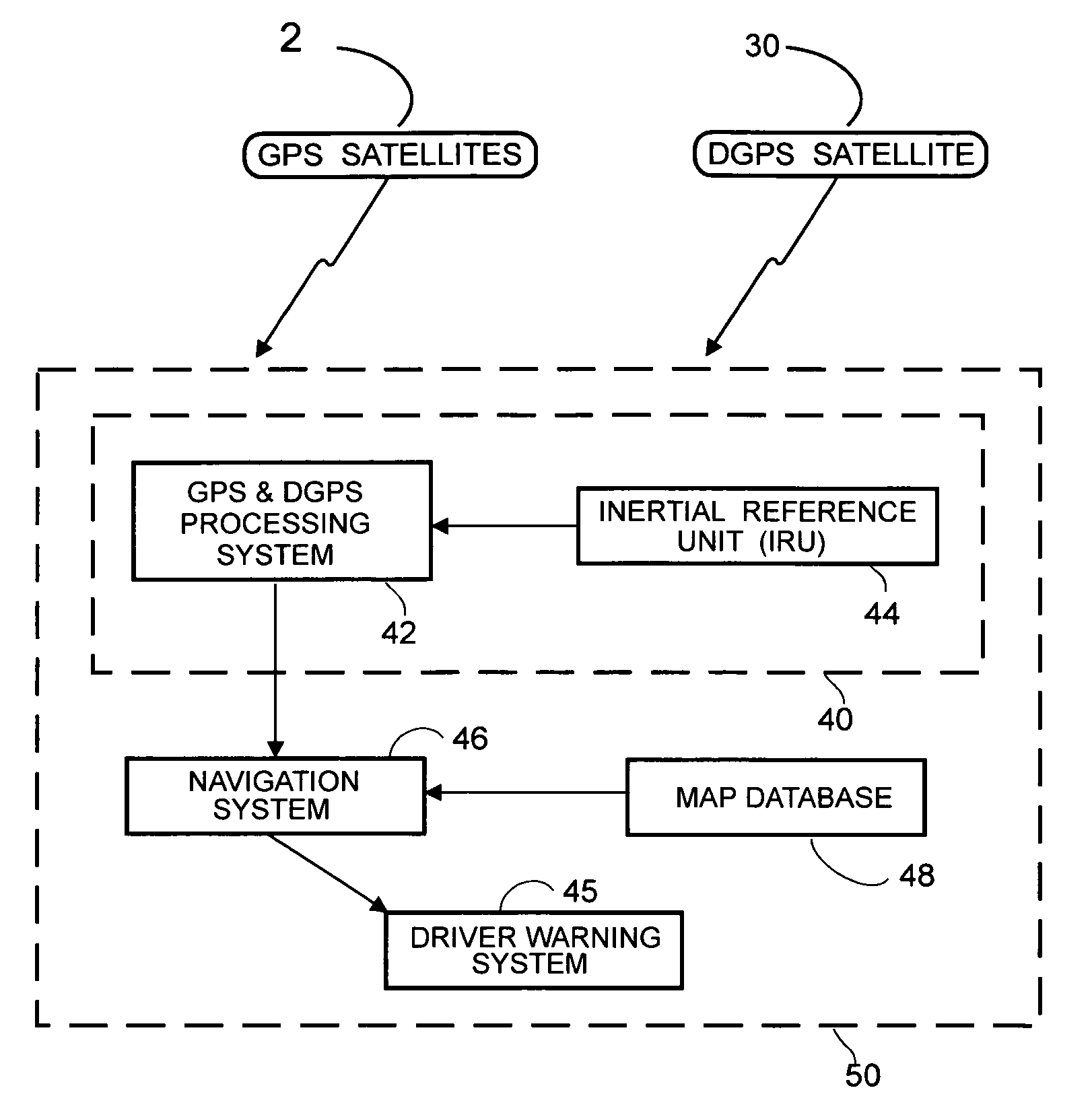
[0144]The RtZF™ system in accordance with the present invention satisfies all of these goals at a small fraction of the cost of prior art systems. The safety benefits have been discussed above. The capacity increase is achieved by confining vehicles to corridors where they are then permitted to travel at higher speeds. This can be achieved immediately where carrier phase DGPS is available or with the implementation of the highway located precise location systems as shown in FIG. 11. An improvement is to add the capability for...


PUM


Abstract

Arrangement for transferring information between a vehicle and one or more transmitters separate from the vehicle includes an antenna mounted on the vehicle and capable of receiving radio frequency waves emitted by the transmitter and containing information, a position determining device for determining the position of the vehicle, and a processor coupled to the antenna and the position determining device and arranged to analyze the waves received by the antenna, determine whether any received waves contain information of interest for operation of the vehicle based on the vehicle's position as determined by the position determining device, and extract the information of interest only from the received waves determined to contain information of interest. The information of interest may be information about the transmitter such as its location, speed, velocity, etc., or information relating to road conditions, weather and the like.

Description

CROSS REFERENCE TO RELATED APPLICATIONS[0001]This application is a continuation-in-part of U.S. patent application Ser. No. 10 / 822,445 filed Apr. 12, 2004 now U.S. Pat. No. 7,085,637 which is a continuation-in-part of[0002]1) U.S. patent application Ser. No. 10 / 118,858 filed Apr. 9, 2002, now U.S. Pat. No. 6,720,920; and[0003]2) U.S. patent application Ser. No. 10 / 216,633 filed Aug. 9, 2002, now U.S. Pat. No. 6,768,944, which is a continuation-in-part of U.S. patent application Ser. No. 10,118,858 filed Apr. 9, 2002, now U.S. Pat. No. 6,720,920.[0004]All of the above applications are incorporated by reference herein.FIELD OF THE INVENTION[0005]The present invention relates to the fields of automobile safety, intelligent highway safety systems, accident avoidance, accident elimination, collision avoidance, blind spot detection, anticipatory sensing, automatic vehicle control, intelligent cruise control, vehicle navigation, vehicle-to-vehicle communication, vehicle to non-vehicle comm...

Claims


Application Information

Patent Timeline
Patent Type & Authority Patents(United States)
IPC IPC(8): G01C21/28B60Q1/00G06F19/00
CPCB60N2/2863B60W30/04B60W30/16B60W30/18154B60W40/06B60W50/00G01S13/931G01S17/023G01S17/89G01S19/17G01S19/42G01S19/50G05D1/0246G05D1/0274G05D1/0278G08G1/16G08G1/161G08G1/163G08G1/164G01S2013/9382B60W10/18B60W10/20B60W30/02B60W30/14B60W30/18172B60W40/072B60W40/076B60W50/14B60W2050/0071B60W2050/0073B60W2050/0078B60W2550/402G01S19/41G01S2013/9339G01S2013/9342G01S2013/9346G01S2013/935G01S2013/936G05D1/0221G05D1/0225G05D1/0257G05D1/027G05D2201/0213G01S2013/9321G01S2013/9332G01S2013/9353G01S2013/9357G01S2013/9375G01S2013/9378B60W10/06G08G1/165G08G1/166G08G1/167G01S2013/9319G01S2013/9315G01S2013/9316G01S2013/9318G01S2013/9322G01S2013/9329G01S2013/93273G01S2013/93185G01S2013/93272G01S2013/93271G01S2013/932G01S17/86B60W2556/50B60W2050/0075B60W30/18159
Inventor BREED, DAVID S.DUVALL, WILBUR E.JOHNSON, WENDELL C.LUKIN, KOSTYANTYN ALEXANDROVICHKONOVALOV, VLADYMYR MICHAILOVICH
Owner AMERICAN VEHICULAR SCI
Why Eureka
Try Eureka