Method of applying parametric oscillators to model dielectric functions

a parametric oscillator and dielectric function technology, applied in the field of modeling data, can solve the problems of insufficient flexibility to accurately fit existing dielectric functions, inability to describe direct-energy-band gap spectral regions, and needing extra fictitious oscillators

Active Publication Date: 2006-09-19
J A WOOLLAM CO
View PDF7 Cites 11 Cited by
  • Summary
  • Abstract
  • Description
  • Claims
  • Application Information

AI Technical Summary

Benefits of technology

[0059]Conventional practice typically involves inspection of Dielectric Function (e2) vs. photon energy to determine the location(s) at which “Dependent Variable Peaks” exist. Use of plotted Dependent vs. Independent Variable data is useful in performing this inspection. The independent variable “Center Point” of an oscillator Structure is then located at the photon energy corresponding to each Peak, with Polynomial Modeled Tails projecting to one or both sides thereof. An Oscillator Structure Finite Magnitude Discontinuity might also be positioned at a Center Point. (In the case where a Dependent Variable Peak corresponds to the Band-Gap Edge in a Semiconductor, Dielectric Function Component Magnitudes often demonstrate essentially Discontinuous “Jumps” over very small changes in Energy, at a photon energy corresponding to the edge of said Band-Gap. The inclusion of Finite Magnitude Discontinuities in the Model speaks to Sixth (6) Requirement recited in the Background Section of this Disclosure in which it is stated that a Model might provide physically relevant parameters therein, eg. a Bandgap absorption edge). Also, each Finite Width Oscillator Structure so positioned will begin and end at an independent variable (e2) value of zero (0), which zero (0) values are, (assuming more than one Oscillator Structure is present), located at the Center Point Energy of a positioned Oscillator Structure, which, as alluded to above, can be the same or another Oscillator Structure. This approach to locating the beginnings and ends of Oscillator Structures positioned on a plot of (e2) vs. photon energy, at the Center Point Energy of other Oscillator Structures, allows moving a Center Point Energy position in relation to other Center Point Energy positions without causing drastic effects in Model produced results at distal photon energies. This approach to locating lower and upper energy end-points of Oscillator Structures is absolutely essential to application of the present invention.

Problems solved by technology

The Forouhi and Bloomer model, however, has been found to have insufficient flexibility to fit existing dielectric functions accurately enough for ellipsometric modeling.
These models have been used to fit measured ellipsometric data, however, they are incapable of describing direct-energy-band-gap spectral regions, and they require extra fictitious oscillators to fill in the absorbtion between (CP's).
Furthermore, attempts at fitting all coefficients simultaneously (as necessary for direct ellipsometer data fitting), are unlikely to succeed because of the highly correlated nature of the functions internal to the model.
The internal coefficients are delicately balanced to produce the proper output, and small changes in (CP) energies can cause large deviations in the model output.

Method used


Image

  • Method of applying parametric oscillators to model dielectric functions
  • Method of applying parametric oscillators to model dielectric functions
  • Method of applying parametric oscillators to model dielectric functions

Examples


Embodiment Construction

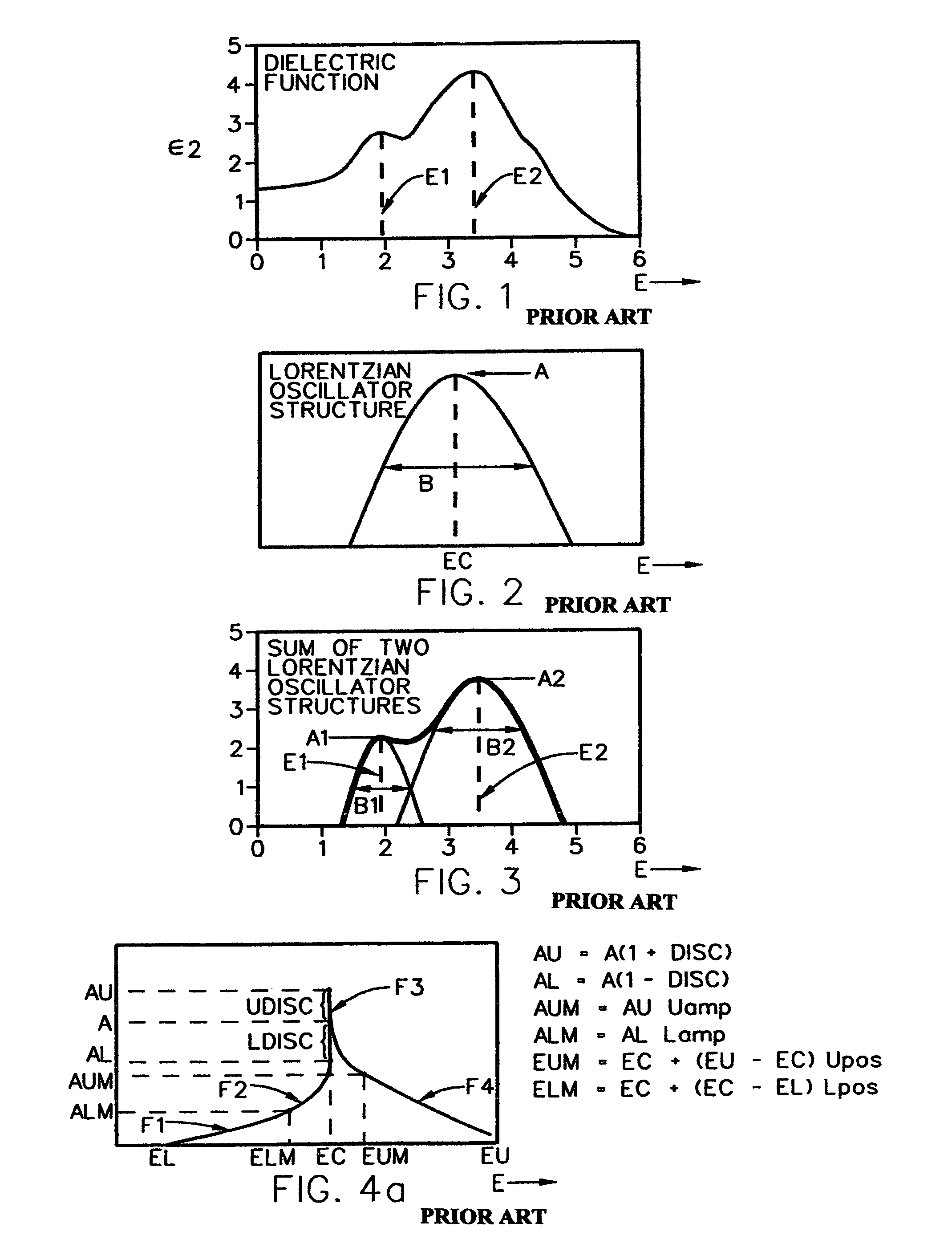
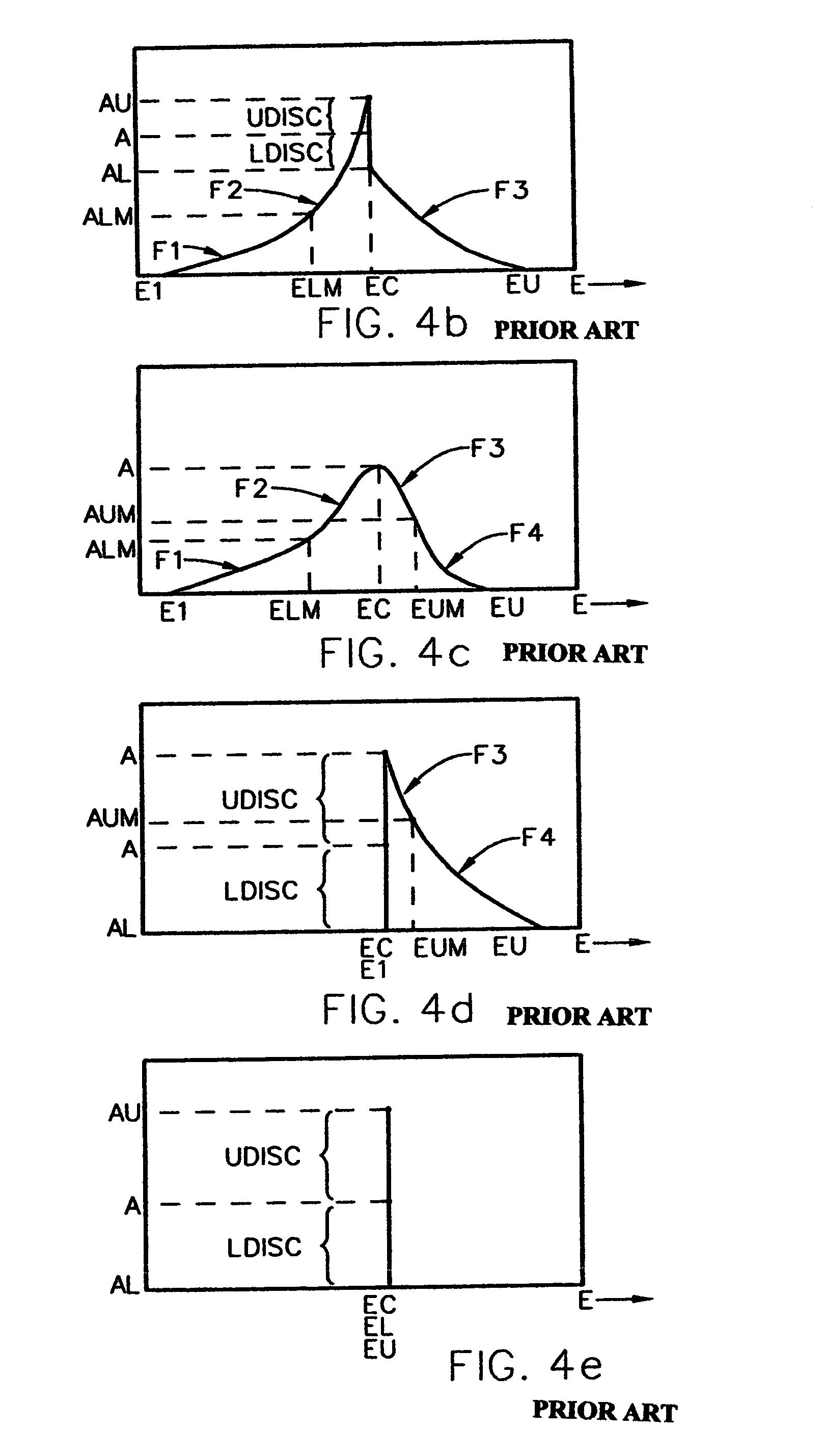
[0076]It is announced at this point that FIGS. 1–4e and 5 and 6 are incorporated from U.S. Pat. No. 5,796,983 for general insight, FIGS. 4f–4k identify additional oscillator structures which can be applied in present invention, and FIGS. 7–8k demonstrate the presently disclosed invention methodology.

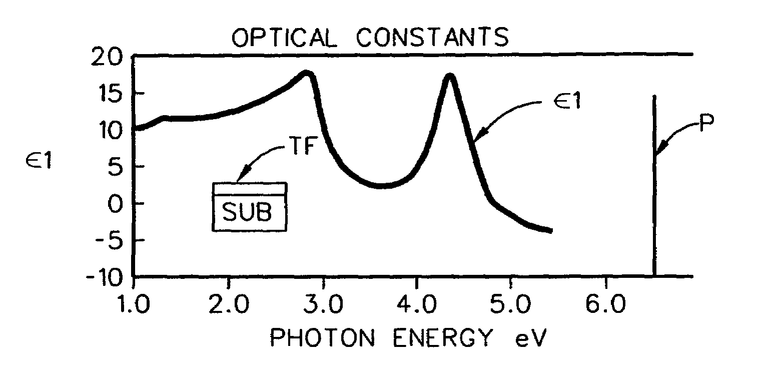
[0077]As disclosed in U.S. Pat. No. 5,796,983 and included herein for background and insight, there is shown in FIG. 1, a plot of data corresponding to the Imaginary Component (e2) of a presumed Dielectric Function vs. Energy, which plot is representative of that which might be obtained from investigation of a semiconductor material. Note the presence of two dependent variable “Peak” regions, located at “E1” and “E2” on the independent variable “X” axis. Next, FIG. 2 shows the general shape of a Narrow Lorentzian or Gaussian Oscillator Structure centered about a point labeled “EC” on the independent variable “X” axis. (While not shown other Mathematical “Oscillator Structures” could also...


PUM


Abstract

Methodology for segmentally modeling Real and Imaginary Parts of Optical Constants or Dielectric Functions using Kroneig-Kramer (K-K) Consistant Oscillators with substantially definite start and end points.

Description

[0001]This Application claims benefit of Provisional Application Ser. No. 60 / 471,753 Filed May 20, 2003.TECHNICAL FIELD[0002]The present invention comprises methodology for modeling data, and more particularly a method for segmentally modeling Real and Imaginary Parts of Optical Constants or Dielectric Functions using Kramers-Kronig (K-K) Consistant Oscillators that have substantially definite start and end points.BACKGROUND[0003]Empirical investigation of substrate systems allows determination of the thicknesses of, and associated optical property component values, (eg. refractive index (n) and extinction coefficient (k), or mathematically equivalent real (e1) and imaginary (e2) complex dielectric function values), for films thereon.[0004]Optical property component values for substrate systems can be empirically obtained by many methods, such as those utilizing substrate system film effected changes caused in reflected and / or transmitted light beam intensities, and those utilizing ...

Claims


Application Information

Patent Timeline
Patent Type & Authority Patents(United States)
IPC IPC(8): G01B7/02
CPCG01N21/41G01B11/0625
Inventor TIWALD, THOMAS E.
Owner J A WOOLLAM CO
Why Eureka
Try Eureka