Method for controlling the temperature of an emission control device

a technology of emission control device and temperature control, which is applied in the direction of electric control, ignition automatic control, machines/engines, etc., can solve the problem of reducing the device temperature below the required temperature for proper operation, and achieve the effect of increasing the temperature of the devi

Inactive Publication Date: 2006-09-26
FORD GLOBAL TECH LLC
View PDF182 Cites 43 Cited by
  • Summary
  • Abstract
  • Description
  • Claims
  • Application Information

AI Technical Summary

Benefits of technology

[0006]By changing the engine operating mode, it is possible to increase temperature of the device back toward a desired operating temperature. For example, by operating the combusting cylinders rich, the excess reactants can react with the oxygen from the first cylinder group, thereby generating heat.

Problems solved by technology

In other words, the high flow rate of gasses may carry away most of the heat, thereby reducing the device temperature below a required temperature for proper operation.

Method used


Image

  • Method for controlling the temperature of an emission control device
  • Method for controlling the temperature of an emission control device
  • Method for controlling the temperature of an emission control device

Examples


Embodiment Construction

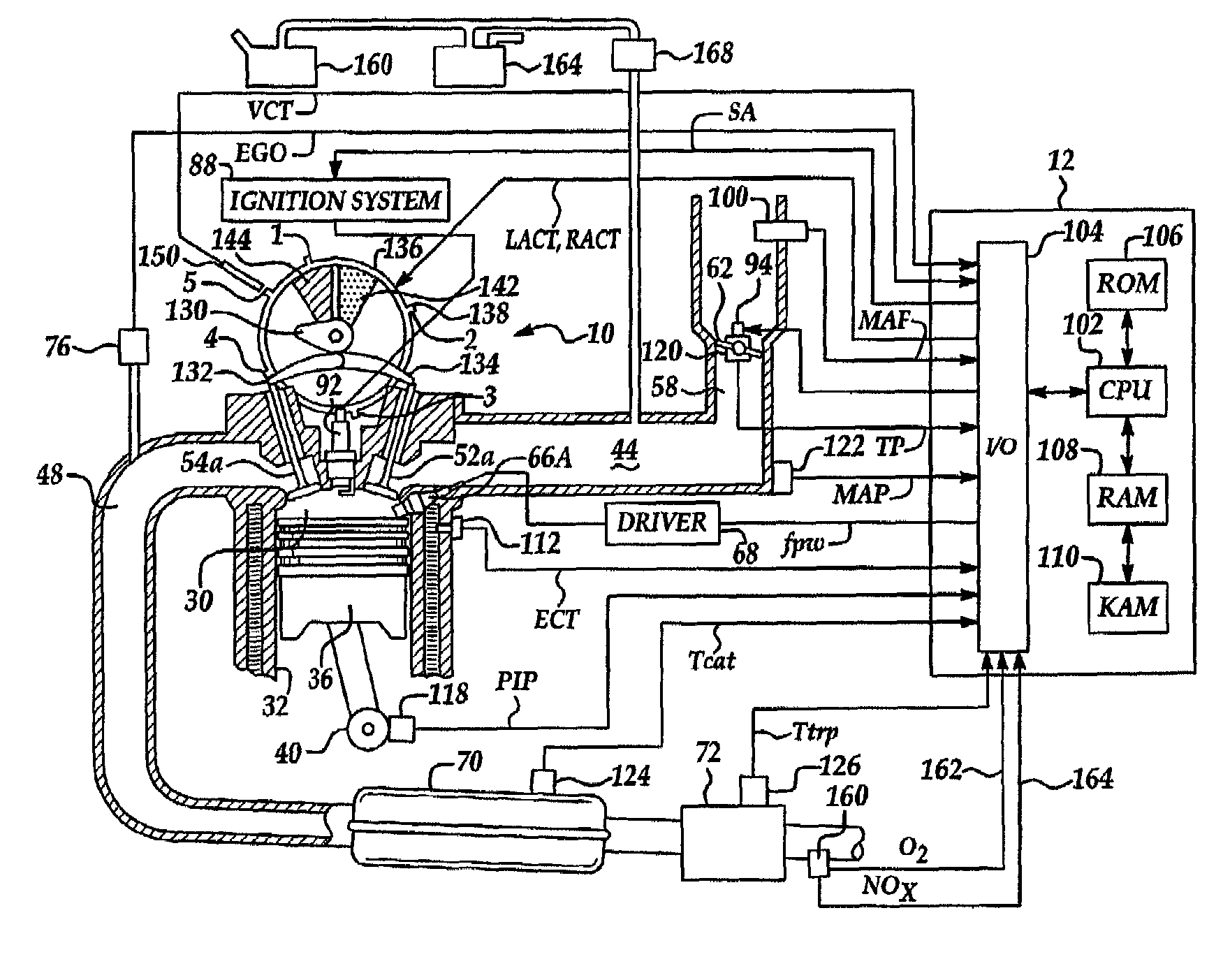
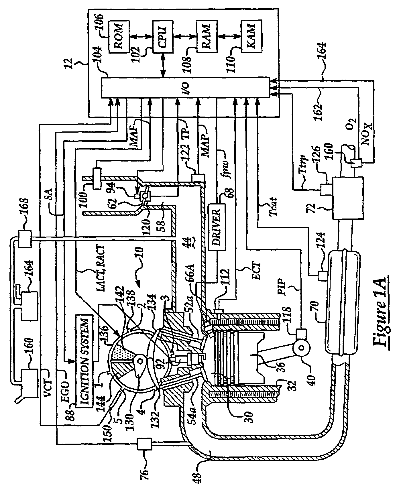
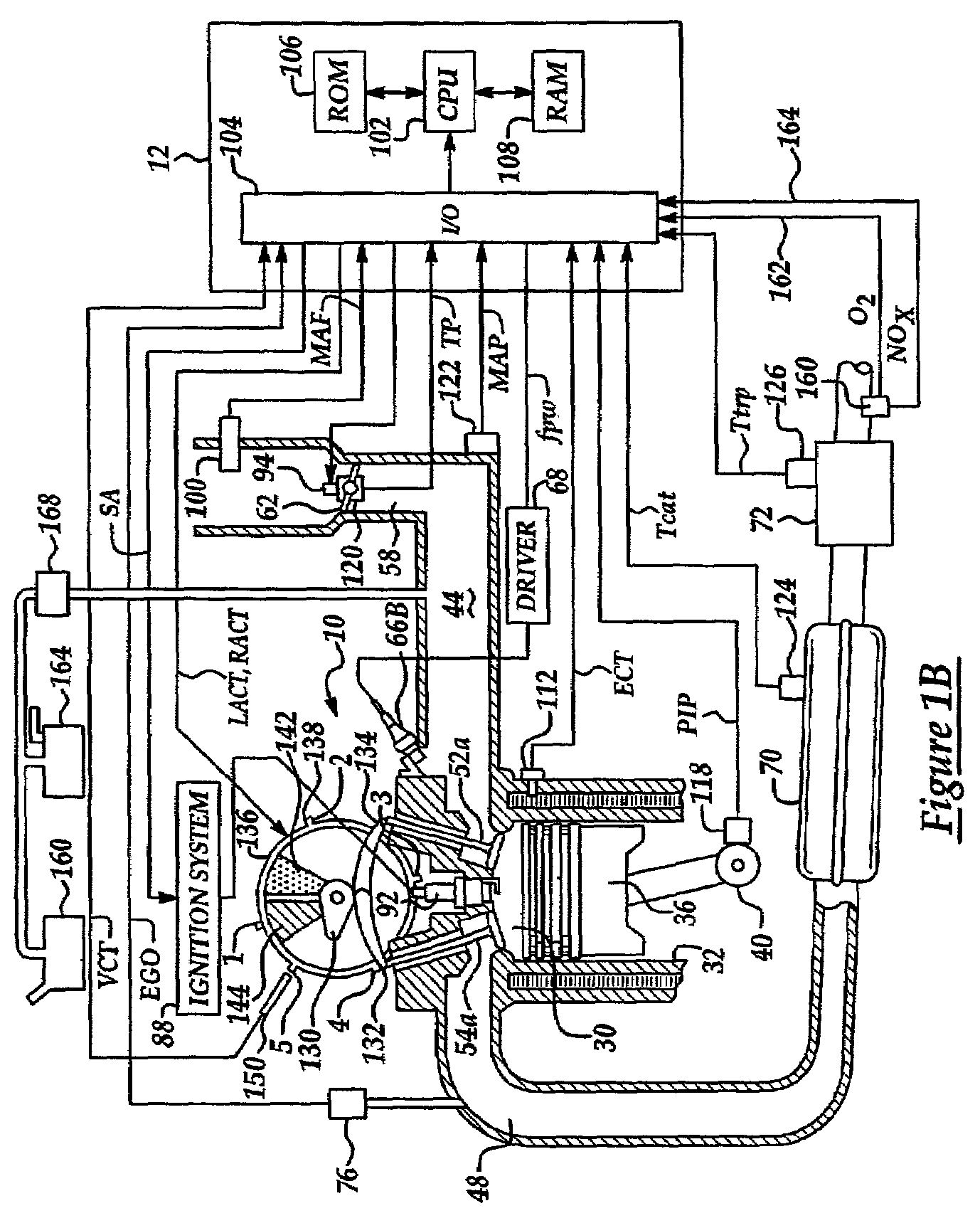
[0041]FIGS. 1A and 1B show one cylinder of a multi-cylinder engine, as well as the intake and exhaust path connected to that cylinder. As described later herein with particular reference to FIG. 2, there are various configurations of the cylinders and exhaust system.

[0042]Continuing with FIG. 1A, direct injection spark ignited internal combustion engine 10, comprising a plurality of combustion chambers, is controlled by electronic engine controller 12. Combustion chamber 30 of engine 10 is shown including combustion chamber walls 32 with piston 36 positioned therein and connected to crankshaft 40. A starter motor (not shown) is coupled to crankshaft 40 via a flywheel (not shown). In this particular example, piston 36 includes a recess or bowl (not shown) to help in forming stratified charges of air and fuel. Combustion chamber, or cylinder, 30 is shown communicating with intake manifold 44 and exhaust manifold 48 via respective intake valves 52a and 52b (not shown), and exhaust valv...


PUM


Abstract

A method is disclosed for controlling operation of an engine coupled to an exhaust treatment catalyst. Under predetermined conditions, the method operates an engine with a first group of cylinders combusting a lean air / fuel mixture and a second group of cylinders pumping air only (i.e., without fuel injection). In addition, the engine control method also provides the following features in combination with the above-described split air / lean mode: idle speed control, sensor diagnostics, air / fuel ratio control, adaptive learning, fuel vapor purging, catalyst temperature estimation, default operation, and exhaust gas and emission control device temperature control. In addition, the engine control method also changes to combusting in all cylinders under preselected operating conditions such as fuel vapor purging, manifold vacuum control, and purging of stored oxidants in an emission control device.

Description

BACKGROUND OF INVENTION[0001]1. Field of the Invention[0002]The field of the invention relates generally to temperature control of an emission control device in an engine exhaust system.[0003]2. Background of the Invention[0004]The inventors herein have developed an engine control methodology that allows efficient engine operation with some of the cylinders inducting air with no injected fuel. However, the inventors have also recognized that such operation may cool an emission control device coupled downstream of the engine. In other words, the high flow rate of gasses may carry away most of the heat, thereby reducing the device temperature below a required temperature for proper operation.SUMMARY OF INVENTION[0005]The above problems are overcome by a method for operating an engine having a first and second group of cylinders in two modes. In the first mode, the first cylinder group operates with air and substantially no injected fuel and the second cylinder group operates by combus...

Claims


Application Information

Patent Timeline
Patent Type & Authority Patents(United States)
IPC IPC(8): F01N3/00F01N3/20F01N11/00F01N13/02F01N13/04F01N13/10F02D37/02F02D41/36F02P5/15
CPCF01N3/2006F01N13/011F02D41/365F02P5/1512F01N13/009F01N13/107F01N2430/02F01N2430/06F01N2430/08F01N2560/026F02D37/02F02D41/1454F02P5/1506Y02T10/46Y02T10/26F01N11/007Y02T10/12Y02T10/40
Inventor SURNILLA, GOPICHANDRA
Owner FORD GLOBAL TECH LLC
Why Eureka
Try Eureka