Dynamic surface element for bodies moving through a fluid

a surface element and fluid technology, applied in special-purpose vessels, vessel construction, transportation and packaging, etc., can solve the problems of increasing drag, increasing costs, and lacking fuel supply, and achieve the effect of more efficient movement of the body

Inactive Publication Date: 2006-09-26
DREWS HILBERT F P
View PDF6 Cites 12 Cited by
  • Summary
  • Abstract
  • Description
  • Claims
  • Application Information

AI Technical Summary

Benefits of technology

[0007]It is a general object of the present invention to provide a body moving through a f...

Problems solved by technology

Without remedial structure to counter this fluid accumulation, drag will increase at a geometrically compounding rate creating an undesirable wake.
In practical term...

Method used


Image

  • Dynamic surface element for bodies moving through a fluid
  • Dynamic surface element for bodies moving through a fluid
  • Dynamic surface element for bodies moving through a fluid

Examples


Embodiment Construction

[0028]Throughout the application, the illustrations demonstrate the essence of the invention, but do not restrict the various other shapes and sizes of other dynamic surface elements used in practice that fall within the purview of the invention.

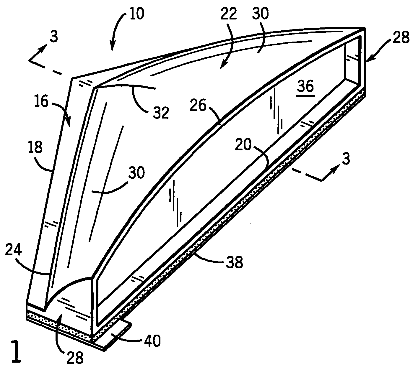
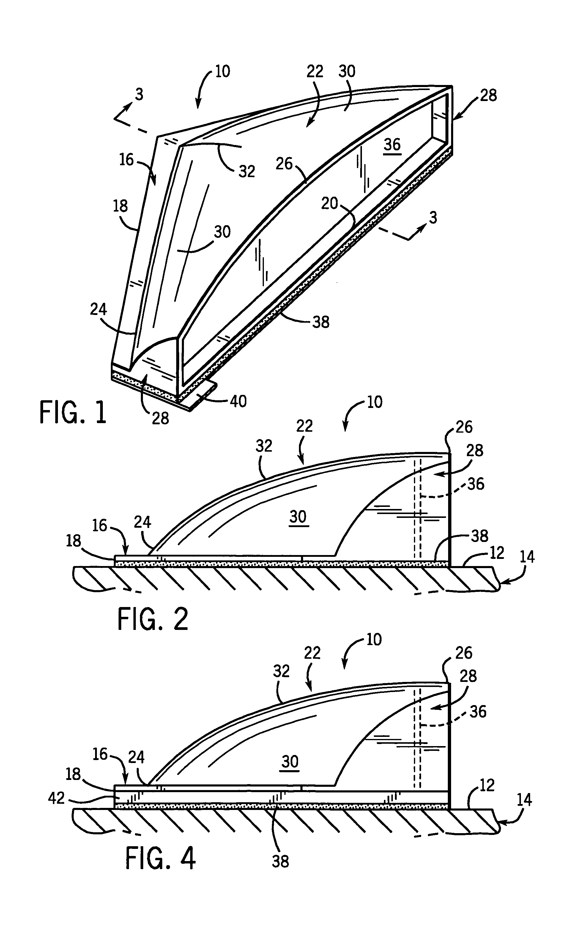
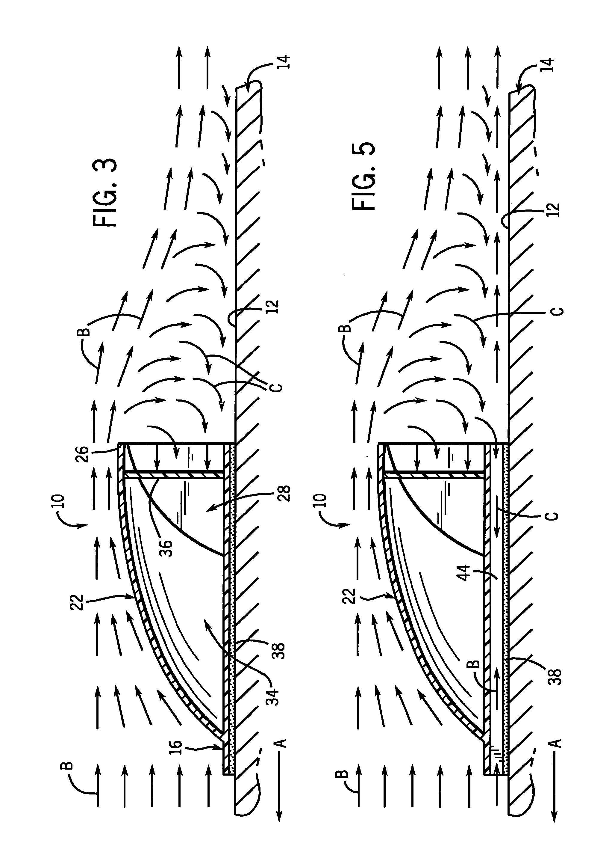
[0029]Referring now to the drawings, FIGS. 1–5 show a preferred embodiment of a dynamic surface element 10 for attaching to and / or modifying a substantially smooth surface 12 of a body 14 moving through a fluid medium, such as air, another gas or water. It is the express purpose of the dynamic surface element 10 to provide a fluid responsive and drag-reducing structure which will promote a more efficient movement of the body 14 through the fluid medium. Unlike prior art dynamic surface structures which generally must be used in various combinations, the dynamic surface element 10 of the present invention 10 is designed as a corrective unit which will enhance movement of the body 14 through a fluid medium when used by itself on the body, as w...


PUM


Abstract

A dynamic surface element is located on a substantially smooth surface of a body moving through a fluid for improving the movement of the body. The dynamic surface element includes a lower wall provided on the surface of the body, the lower wall having a front edge extending rearwardly to a back edge. An upper wall rises upwardly and rearwardly from the lower wall with the upper wall having a lower edge connected to the lower wall, and an upper edge spaced above the lower wall. A pair of sidewalls connects the upper and lower walls and together with the upper and lower walls forms a chamber accumulating internal pressure offset by external pressure caused by fluid flow against and over the upper wall as the body moves. The dynamic surface element interrupts layers of fluid normally accumulating on the smooth surface of the body moving through the fluid and creating drag. A major portion of the fluid flowing over and rearwardly of the upper wall is reversed and captured due to internal and external pressure differential in the chamber to reduce drag, and simultaneously act against rear surfaces of the dynamic surface element to define a propulsive force assisting movement of the body.

Description

FIELD OF THE INVENTION[0001]This invention relates broadly to a surface attachment to or modification of a body for improving the movement of the body in a fluid medium.BACKGROUND OF THE INVENTION[0002]Prior U.S. patents and other literature disclose utilization of various surface configurations for reducing of the drag and / or creating of various forces on the surface of a moving body such as an automobile, boat, airplane or other devices having a surface which moves through air, water or other fluids.[0003]The present inventor's U.S. Pat. No. 4,284,302 (issued Aug. 18, 1981) and U.S. Pat. No. 5,988,568 (issued Nov. 23, 1999) disclose surface modifications to a body to improve the efficient movement through a fluid. Both patents disclose air directing flutes which are laterally and longitudinally spaced and distributed over a surface to improve the efficiency of movement in fluid mediums.[0004]As noted in those patents and others, there is a continuing demand for practical construct...

Claims


Application Information

Patent Timeline
IPC IPC(8): B63B1/34
CPCB62D35/00F15D1/10Y02T70/121B63B1/34Y02T70/10
Inventor DREWS, HILBERT F. P.
Owner DREWS HILBERT F P
Why Eureka
Try Eureka