
Breaking hammer, and fastening element, side plate, and protective casing of breaking hammer

a technology of breaking hammer and fastening element, which is applied in the direction of drilling machine and method, mechanical machine/dredger, portable percussive tools, etc., can solve the problems of only being suited for use, and affecting the use effect of breaking hammer

Inactive Publication Date: 2006-09-26
SANDVIK TAMROCK
View PDF23 Cites 7 Cited by
  • Summary
  • Abstract
  • Description
  • Claims
  • Application Information

AI Technical Summary

Benefits of technology

"The present invention provides a novel and improved breaking hammer with a fastening element, side plate, and protective casing for fastening it to a work machine. The breaking hammer has at least two alternative fastening means for fastening it to the work machine, including a flange mounting and a pin mounting. The fastening element has at least one first and second projection arranged at a distance from each other with a substantially empty space between them, which can be used for flange mounting or pin mounting. The top part of the breaking hammer has at least one plane surface against which a flange can be arranged for a flange mounting. The side plate has at least two alternative fastening means for fastening the breaking hammer to the work machine. The protective casing has at least two alternative fastening means for fastening it to the work machine. The invention provides the advantage of reducing manufacturing costs and allowing more flexible and efficient use of the breaking hammer."

Problems solved by technology

As the percussion piston strikes, the tool is pressed against the material to be broken, whereby, due to the impact and pressing, the tool penetrates the material to be handled and breaks it.
This is difficult, because breaking hammers then need to be manufactured with various fastening elements, which naturally increases manufacturing costs.
Another drawback is that the breaking hammer is only suited for use in work machines employing the fastening system in question.

Method used


Image

  • Breaking hammer, and fastening element, side plate, and protective casing of breaking hammer
  • Breaking hammer, and fastening element, side plate, and protective casing of breaking hammer
  • Breaking hammer, and fastening element, side plate, and protective casing of breaking hammer

Examples


Embodiment Construction

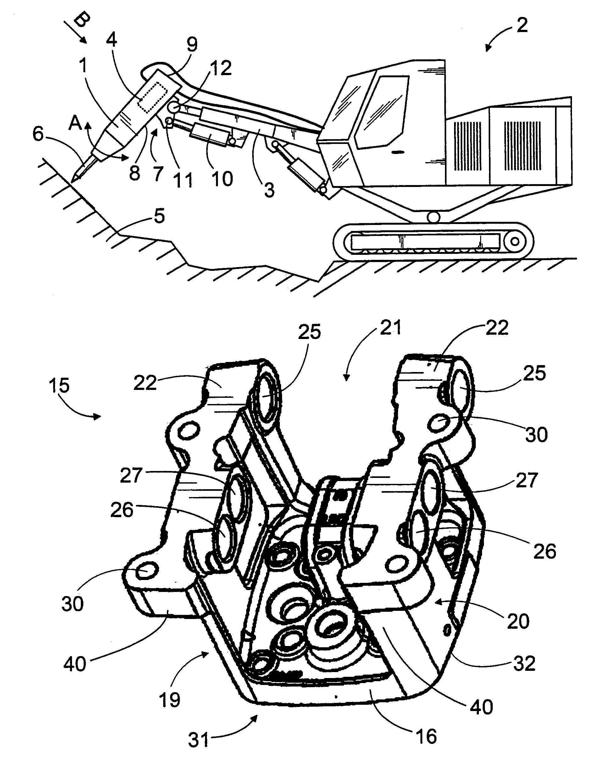
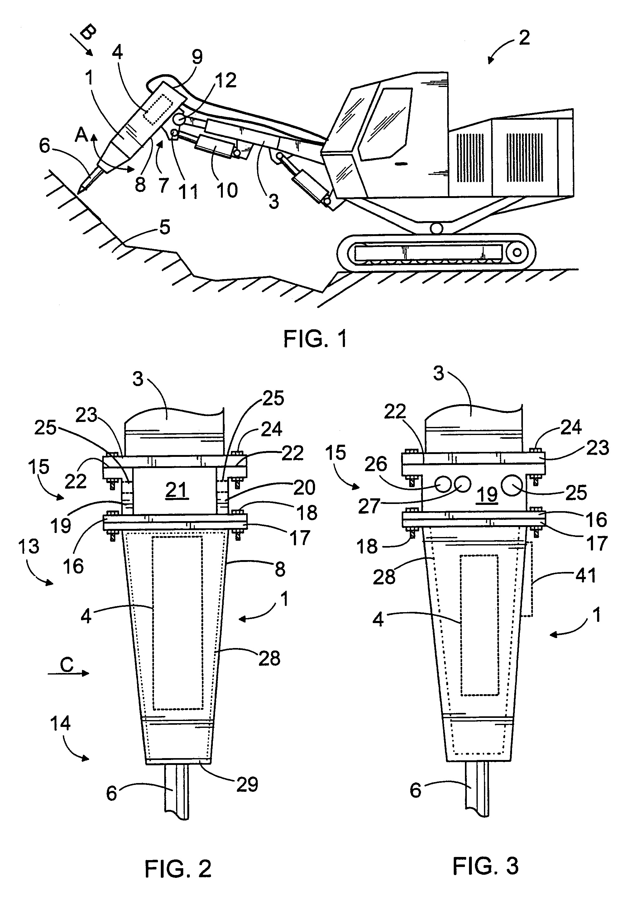
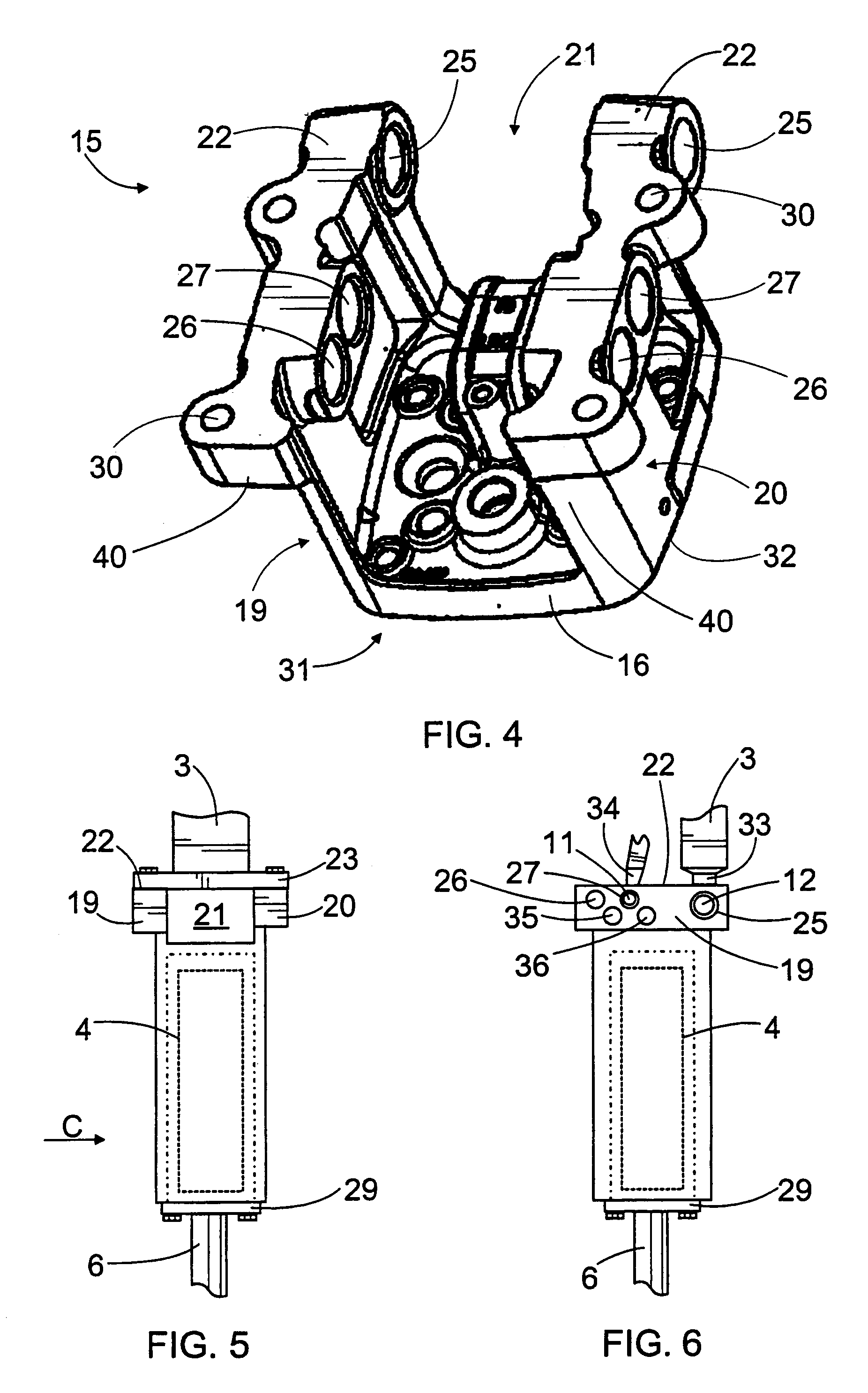
[0024]In FIG. 1, a breaking hammer 1 is arranged at the free end of an excavator 2 boom 3. The breaking hammer 1 can be arranged to any movable work machine or to a boom, for instance, that is mounted on a fixed platform. The breaking hammer 1 has a percussion device 4 for generating impact pulses. The breaking hammer 1 is pressed by means of the boom 3 against a material 5 to be broken as the percussion device 4 strikes a tool 6 connected to the breaking hammer 1, which transmits the impacts to the material 5 to be broken. The percussion device 4 of the breaking hammer 1 may be hydraulic, whereby it may be connected to the hydraulic system of the excavator 2. The percussion device 4 may also be of some other type, such as electric. The impact pulses may be generated in other ways than with a reciprocating percussion piston.

[0025]The breaking hammer 1 comprises a fastening element 7, by means of which it can be fastened to the outermost end of the boom 3. The fastening element 7 may...


PUM

PropertyMeasurementUnit
distanceaaaaaaaaaa
structureaaaaaaaaaa
hydraulic pressureaaaaaaaaaa

Abstract

A crushing hammer, and a fastening element, side plate, and protective casing for the crushing hammer. The crushing hammer comprises at least two alternative fastening elements with which it can be fastened to a boom of a work machine. The fastening can be done with a separate fastening element that is equipped with a plane surface for flange mounting and openings for a pin mounting. The fastening elements may also be formed to side plates, between which the crushing hammer is arranged. The fastening elements may further be integrated to the protective casing.

Description

BACKGROUND OF THE INVENTION[0001]The invention relates to a breaking hammer comprising: a percussion device arranged to generate impact pulses to a tool connectable to the breaking device, and fastening means in the top part of the breaking hammer for fastening the breaking hammer to a work machine. The invention further relates to a fastening element, a side plate, and a protective casing of a breaking hammer.[0002]A breaking hammer is used as an auxiliary device to an excavator or some other work machine when breaking rock, concrete or some other relatively hard material. The breaking hammer has a percussion device that strikes a tool fastened to the breaking hammer, which transmits the percussions on to the material to be broken. A percussion device is generally hydraulic and has a percussion piston that makes a reciprocating movement caused by hydraulic pressure and strikes an impact surface at the top end of the tool. As the percussion piston strikes, the tool is pressed agains...

Claims


Application Information

Patent Timeline
Patent Type & Authority Patents(United States)
IPC IPC(8): B25D17/28E02F3/36E02F3/96
CPCE02F3/966E02F3/3604E02F3/36E21B10/36
Inventor SILTANEN, OLLITEELAHTI, TEEMU
Owner SANDVIK TAMROCK
Learn More