Braking surface cooling assembly and brake performance enhancing methods

a technology of friction brakes and cooling assemblies, which is applied in the direction of friction actuated brakes, brake discs, transportation and packaging, etc., can solve the problems of reducing or diminishing kinetic energy, limiting the effectiveness of dispersing such thermal energy to the atmosphere, and the heat sink capacity of the assembly being the peak use limit factor, so as to reduce or diminish the function and role of the heat sink rotor, the effect of reducing or diminishing the weight of the rotor

Inactive Publication Date: 2006-09-26
OROURKE THOMAS W
View PDF12 Cites 22 Cited by
  • Summary
  • Abstract
  • Description
  • Claims
  • Application Information

AI Technical Summary

Benefits of technology

[0014]The rotational braking surface cooling assembly of this invention is adaptable for use in association with a most common varieties of vehicle brake assemblies that include a nonrotational mounting support, a rotary braking surface having a normal forward direction of rotation, and a friction pad mounted for controlled intermittent engagement with the rotary braking surface. The rotational braking surface cooling assembly has at least one cooling vane and a positioning structure associated with the vane for nonrotational positioning of the vane in an angled disposition relative to the rotational braking surface. The positioning is selected so that the vane can be in position to intercept and redirect (away from the rotational braking surface) the fluid boundary layer, especially at the swept area between the braking surface and the brake assembly friction pad.
[0029]It is yet another object of this invention to provide a method of enhancing the performance of a brake assembly comprising a rotary braking member having a boundary layer including air adhered thereto, at least one nonrotating friction pad mounted for controlled intermittent braking engagement with the rotary braking member, and at least one annular swept area defined on the braking member by the area contactable by the friction pad, the steps of the method including rotating the braking member and adhered boundary layer, parting at least a portion of the rotating boundary layer from the braking member, and guiding the flow of the portion of the boundary layer to a position spaced from the swept area, whereby a cooling flow of air is induced over the braking member.

Problems solved by technology

In all instances the operation of these braking mechanisms will generate thermal energy, often including large quantities of thermal energy, while slowing or stopping the vehicle, thus reducing or diminishing kinetic energy.
The ability to dissipate such thermal energy to the atmosphere is typically the ultimate limiting factor in the effectiveness of a given braking assembly or mechanism, with the heat sink capacity of the assembly being the peak-use-limiting factor.
Friction pads are of lesser mass and in thermal contact with various structures adversely affected by heat.
Often, when air is to be ducted to the rotor, the brake requirements are typically demanding, as in a racing or high performance vehicle.
Weight is generally undesirable in any vehicle, with rotating, unsprung weight being particularly objectionable.
Brakes usually constitute unsprung weight which compromises fuel efficiency, ride and handling.
The energy expended to spin a heavy rotor is generally wasted and adds to the overall energy that the brakes must convert to thermal energy.
Accordingly, such rotors must have considerable mass, and thus be heavy.
Braking effectiveness is easily compromised and may be lost under adverse heat conditions.
While inherent in such conventional designs, this is highly undesirable for several reasons.
Episodes of brake fade are increased and pad wear is substantially accelerated at high temperatures.

Method used


Image

  • Braking surface cooling assembly and brake performance enhancing methods
  • Braking surface cooling assembly and brake performance enhancing methods
  • Braking surface cooling assembly and brake performance enhancing methods

Examples


Embodiment Construction

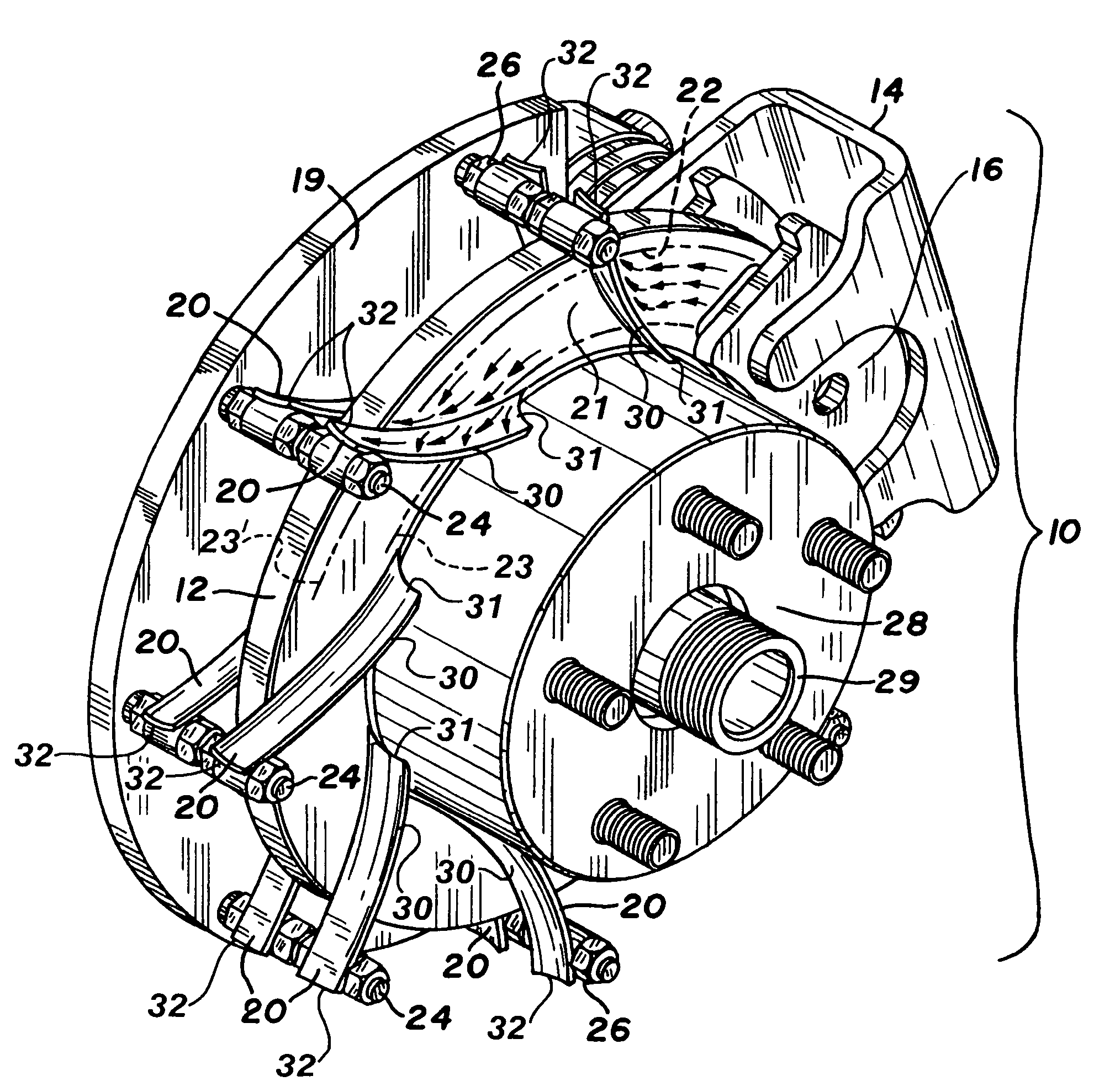
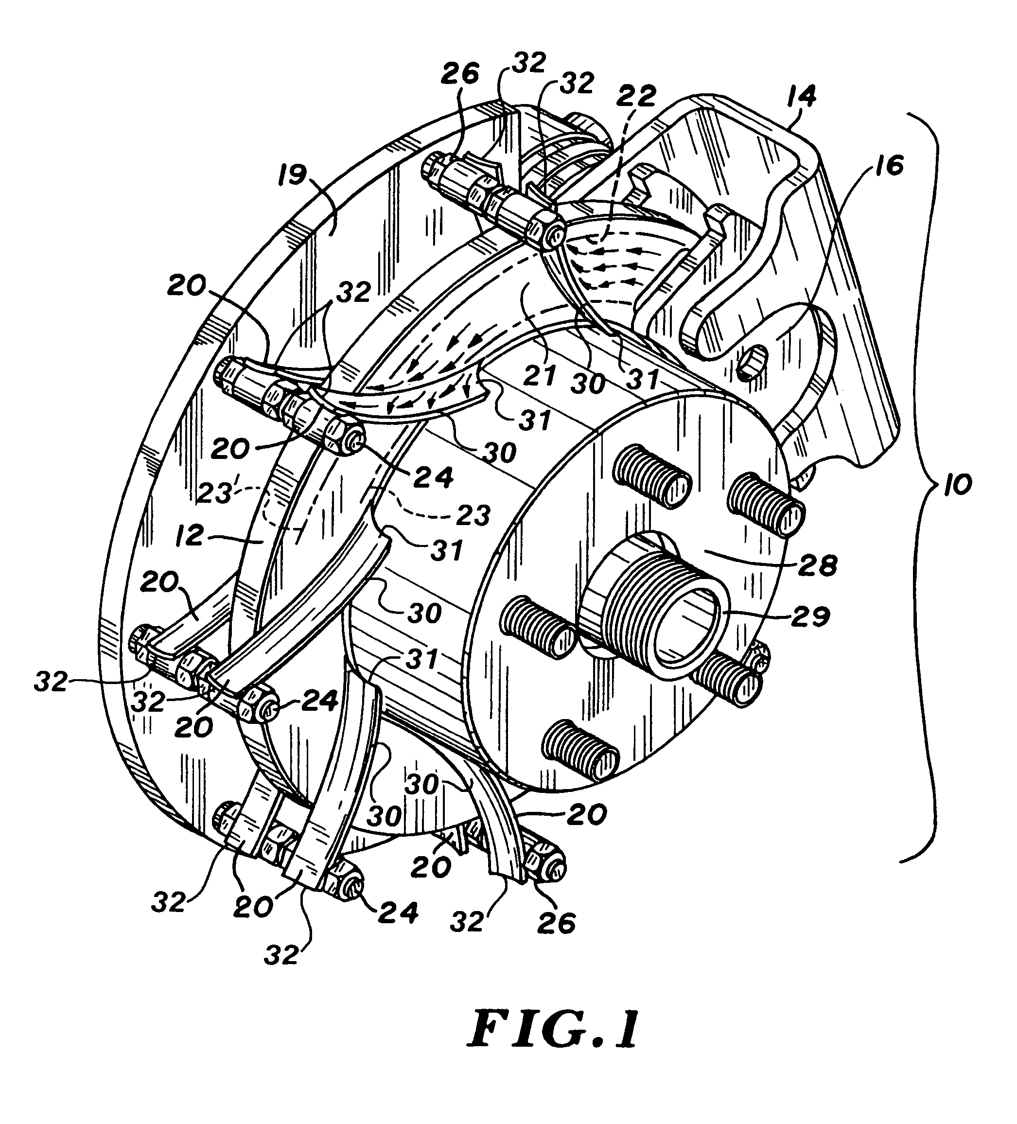
[0041]Turning now to the drawings, in which similar components are designated by like reference numerals throughout the various FIGURES, a brake assembly is shown in FIG. 1 and generally designated by reference numeral 10. As shown, brake assembly 10 includes rotary braking member (rotor 12, for example), caliper 14, friction pad assemblies 16 and backing plate 19 (the term “backing plate” as used herein is intended to be interpreted in a comprehensive sense unless otherwise specifically signified, and accordingly is intended to refer to a variety of closely spaced components which are stationary relative to the rotational motion of the rotor and braking surface, including the mounting plates for the friction pads, that is, in this connection and by way of example, friction pads are frequently mounted upon and / or otherwise secured to the mounting plates).

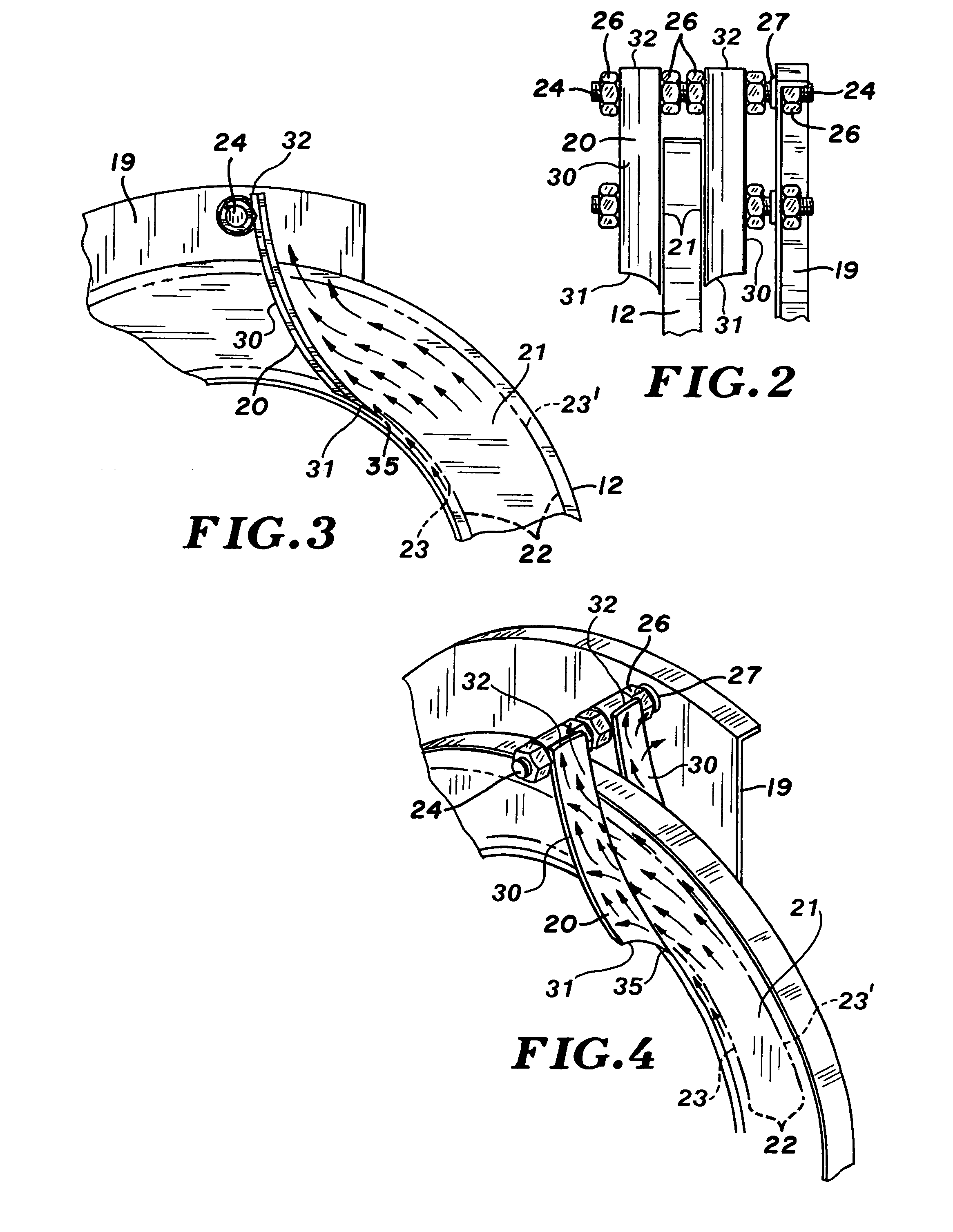
[0042]The cooling assembly of this invention includes fluid guiding cooling vanes 20, shown in the FIGURES as being coupled to a m...


PUM


Abstract

Vanes positioned immediately adjacent the swept area of a moving friction brake rotor induce a flow of air over the rotor by displacing the boundary layer of gases from the rotor surface and conducting such layer along the intercepting surface of the vane, and thus inducing a flow of cooler air over the rotor. Under heavy braking, friction pad particles and substantial quantities of thermal energy in the superheated gases of the boundary layer are removed by the vanes.

Description

FIELD OF THE INVENTION[0001]This invention relates to frictional brake assemblies and methods, and, more particularly, relates to such assemblies or methods providing for increased rate of dissipation of thermal energy to reduce operating temperature.BACKGROUND OF THE INVENTION[0002]Friction brakes are widely used on land and air vehicles as well as with stationary machinery. The following discussion will be largely in the context of the demanding use with high performance land vehicles, but the contemplated utility is with all friction brakes.[0003]Broadly defined, friction brakes function by pressing a friction pad against a moving surface thus converting kinetic energy into thermal energy. Many embodiments of such brakes are well known in the art. The moving surface can be a disc, drum, wheel surface etc., but will be herein referred to generically as a rotor. As is known, the movable friction pads may be carried by calipers or on expanding shoes or the like. Known pad actuating ...

Claims


Application Information

Patent Timeline
Patent Type & Authority Patents(United States)
IPC IPC(8): B60L7/28
CPCF16D65/847F16D65/0037
Inventor O'ROURKE, THOMAS W.
Owner OROURKE THOMAS W
Why Eureka
Try Eureka