Rotor for synchronous induction motor, synchronous induction motor, fan motor, compressor, air conditioner, and refrigerator
a synchronous induction motor and synchronous induction motor technology, applied in the direction of magnetic circuit rotating parts, piston pumps, magnetic circuit shape/form/construction, etc., can solve the problems of low efficiency, reduced generated torque, and insufficient bonding between the rotor and the filler, so as to achieve simple construction and reduce the effect of motor properties
- Summary
- Abstract
- Description
- Claims
- Application Information
AI Technical Summary
Benefits of technology
Problems solved by technology
Method used
Image
Examples
embodiment 1
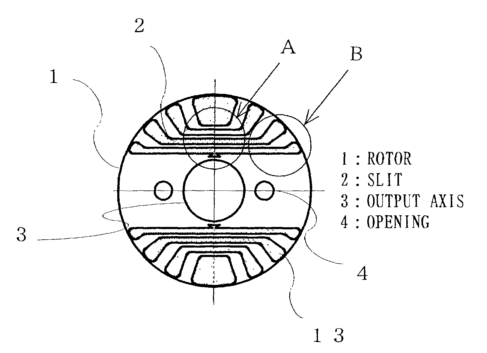
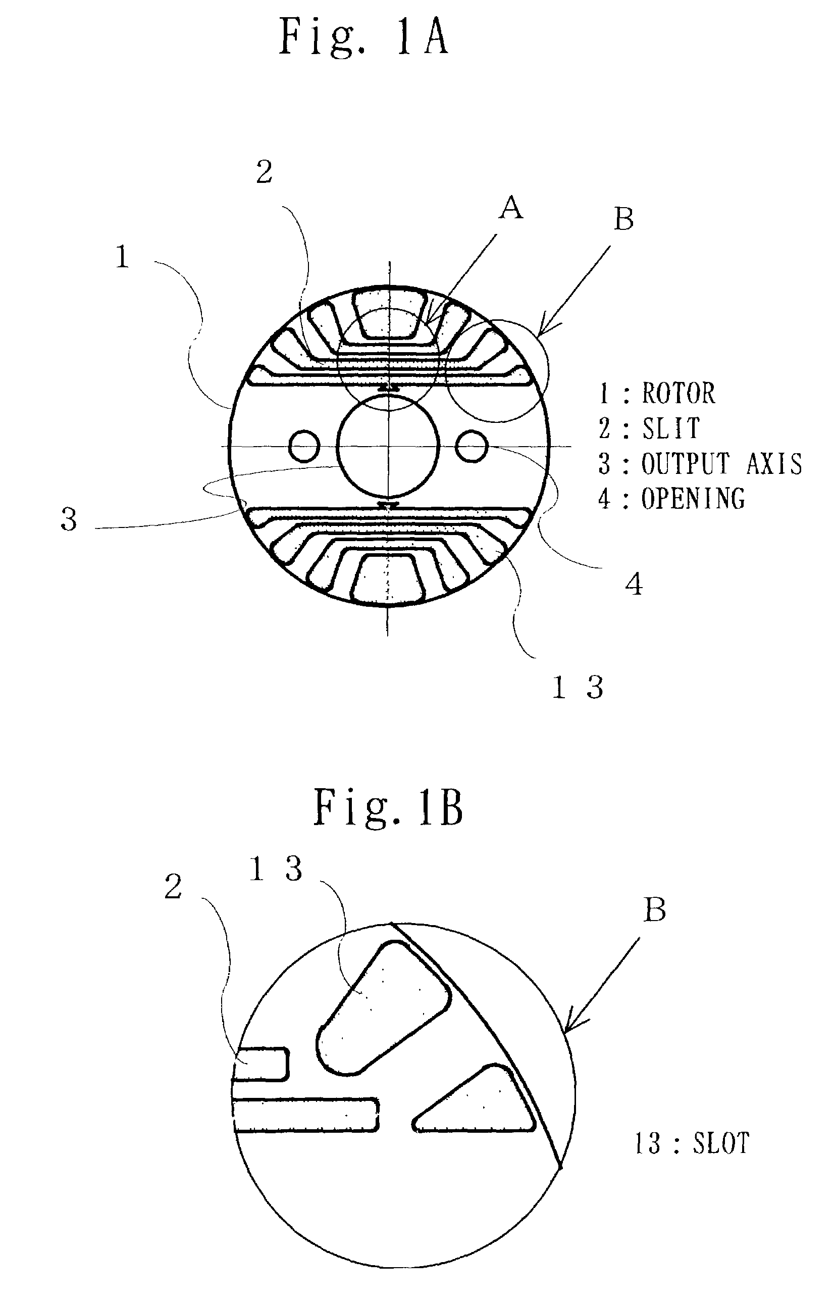
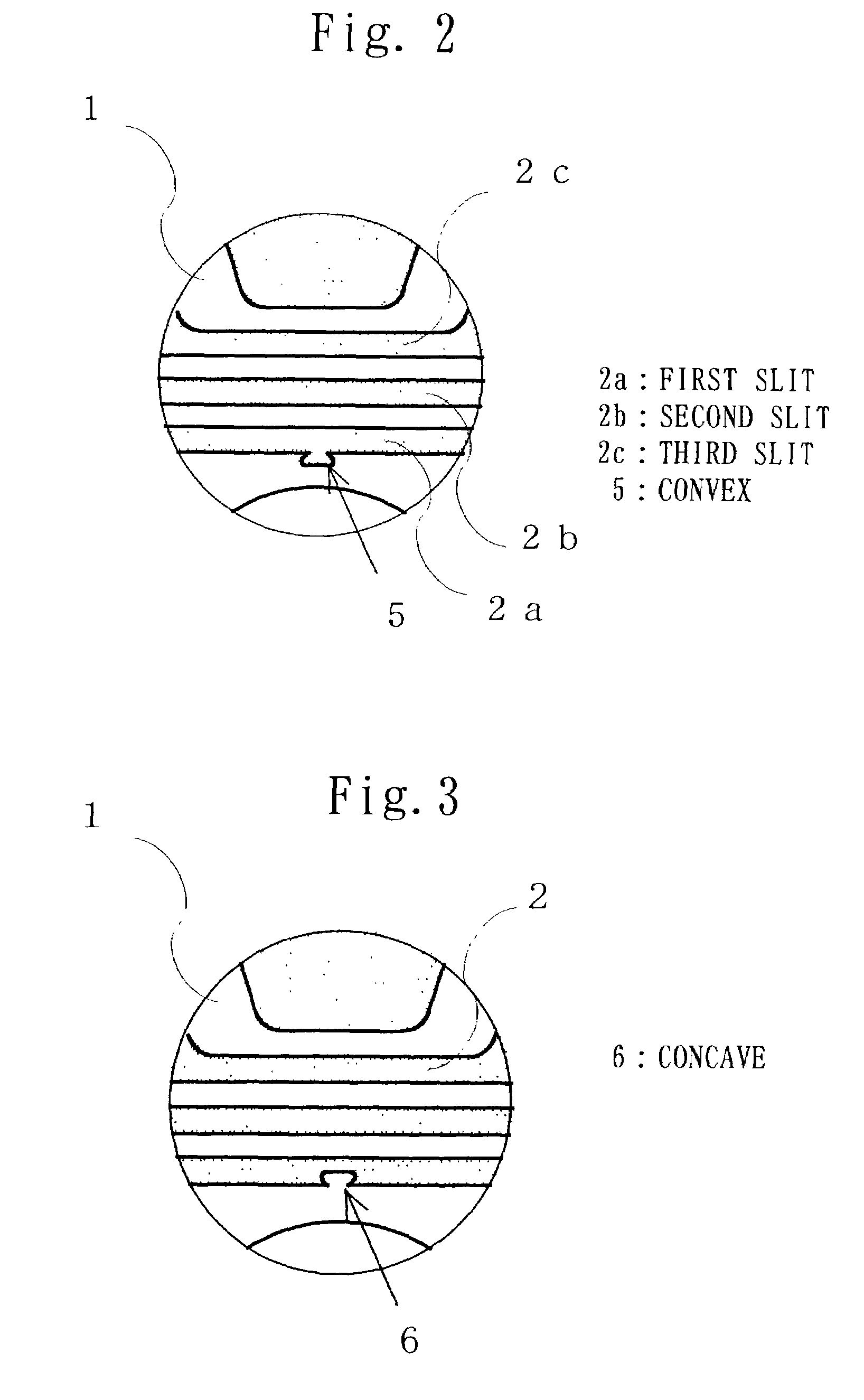
[0089]FIGS. 1A, 1B, 2 and 3 show the first embodiment of the invention: FIG. 1A shows a cross section of a rotor of a synchronous induction motor; FIG. 2 shows an enlarged view of a part A of FIG. 1A in which a slit is provided with a convex; and FIG. 3 shows another enlarged view of the part A of FIG. 1A in which a slit is provided with a concave. In FIGS. 1A and 2, a reference numeral 1 shows a rotor which is fixed to an output axis 3 by such as press-fit and formed by laminating in an axial direction. A reference numeral 13 shows a slot which is filled with nonmagnetic conductive material such as aluminum and is located at a place which is the farthest from a center of the rotor 1 on an inner circumference, so that secondary electric current flows to generate induction torque at start or asynchronous operation of the motor. The slot 13 can be of any shape as long as necessary induction torque can be generated according to specifications of the synchronous induction motor. A refer...
embodiment 2
[0106]FIGS. 4A, 4B, and 4C and FIGS. 5A, 5B, and 5C show the second embodiment of the invention. An element having the same sign as the one as explained in the first embodiment has the same function, so that an explanation is omitted here. FIGS. 4A, 4B, and 4C are enlarged views of the part A of FIG. 1A when a convex or a concave is provided at plural slits, and FIGS. 5A, 5B, and 5C are enlarged views of the part A of FIG. 1A when a convex or a concave provided at the slit has a form being other than a wedge.
[0107]In FIG. 4A, as well as the first embodiment, a convex having a wedge form is provided so that the slit of the rotor 1 is caught by the slit 2a in the direction of the centrifugal force, and the rotor 1 and aluminum of the filler in the slit are mechanically bonded, and another convex having a wedge form is provided at an opposite side of the first slit 2a. In the same way, a convex and a concave are provided at the second slit 2b and the third slit 2c.
[0108]Providing the ...
embodiment 3
[0124]FIGS. 6A and 6B, 7, 8A, 8B, 9A, and 9B show the third embodiment of the invention. An element having the same sign as the one as explained in the first embodiment has the same function, so that an explanation is omitted here. FIGS. 6A and 6B are cross sections of a rotor of a synchronous induction motor; FIG. 7 is a cross section of a rotor of a synchronous induction motor, of which plural slots are filled with supporting member; FIGS. 8A and 8B show fixing member; FIGS. 9A and 9B show a rotor to which the fixing member is fixed.
[0125]In FIGS. 6A and 6B, a reference numeral 14 shows supporting member made of such as SUS (stainless steel) which is inserted into the slot 13. As the rotor 1 rotates, the centrifugal force is generated at the rotor and the stress is acted on each connection part. At this time, some warp is produced on the thin connection part, and the rotor 1 as a whole tends to bulge upward / downward in FIG. 6A.
[0126]As shown in FIG. 6A, the supporting member 14 is...
PUM
 Abstract
Description
Claims
Application Information
 - R&D
- Intellectual Property
- Life Sciences
- Materials
- Tech Scout
- Unparalleled Data Quality
- Higher Quality Content
- 60% Fewer Hallucinations
Browse by: Latest US Patents, China's latest patents, Technical Efficacy Thesaurus, Application Domain, Technology Topic, Popular Technical Reports.
© 2025 PatSnap. All rights reserved.Legal|Privacy policy|Modern Slavery Act Transparency Statement|Sitemap|About US| Contact US: help@patsnap.com


