Resonator piece, resonator, oscillator and electronic device

a resonator and oscillator technology, applied in the direction of oscillator, piezoelectric/electrostrictive/magnetostrictive device, piezoelectric/electrostrictive/magnetostriction machine, etc., can solve the problems of > collapse, and other short circuits high, so as to prevent fluctuations

Active Publication Date: 2006-09-26
SEIKO EPSON CORP
View PDF8 Cites 26 Cited by
  • Summary
  • Abstract
  • Description
  • Claims
  • Application Information

AI Technical Summary

Benefits of technology

[0041]According to the above-described configurations, the width of the base portion side of openings of the groove portions of the resonator piece is formed narrower than the width of other portions, with connection electrode disposition portions for disposing the groove electrode-use connection electrode portions or the side surface electrode-use connection electrode portions being formed near the narrowly formed openings of the groove portions. Thus, by disposing the groove electrode-use connection electrode portions or the side surface electrode-use connection electrode portions at the connection electrode disposition portions, the groove electrode-use connection electrode portions or the side surface electrode-use connection electrode portions can be prevented from short-circuit

Problems solved by technology

There have thus been the problems that, when consideration is given to error in the actual manufacturing process, the side surface electrode-use connection electrodes and the groove electrodes or the groove electrode-use connection electrodes make contact and the potential to cause other short circuits is high, which is a ca

Method used


Image

  • Resonator piece, resonator, oscillator and electronic device
  • Resonator piece, resonator, oscillator and electronic device
  • Resonator piece, resonator, oscillator and electronic device

Examples


Embodiment Construction

[0056]Preferable embodiments of the invention will be described in detail below on the basis of the attached drawings. It should be noted that the embodiments described below are merely preferable specific examples of the invention to which various technically preferable limitations have been added, but the scope of the invention is not limited to these embodiments.

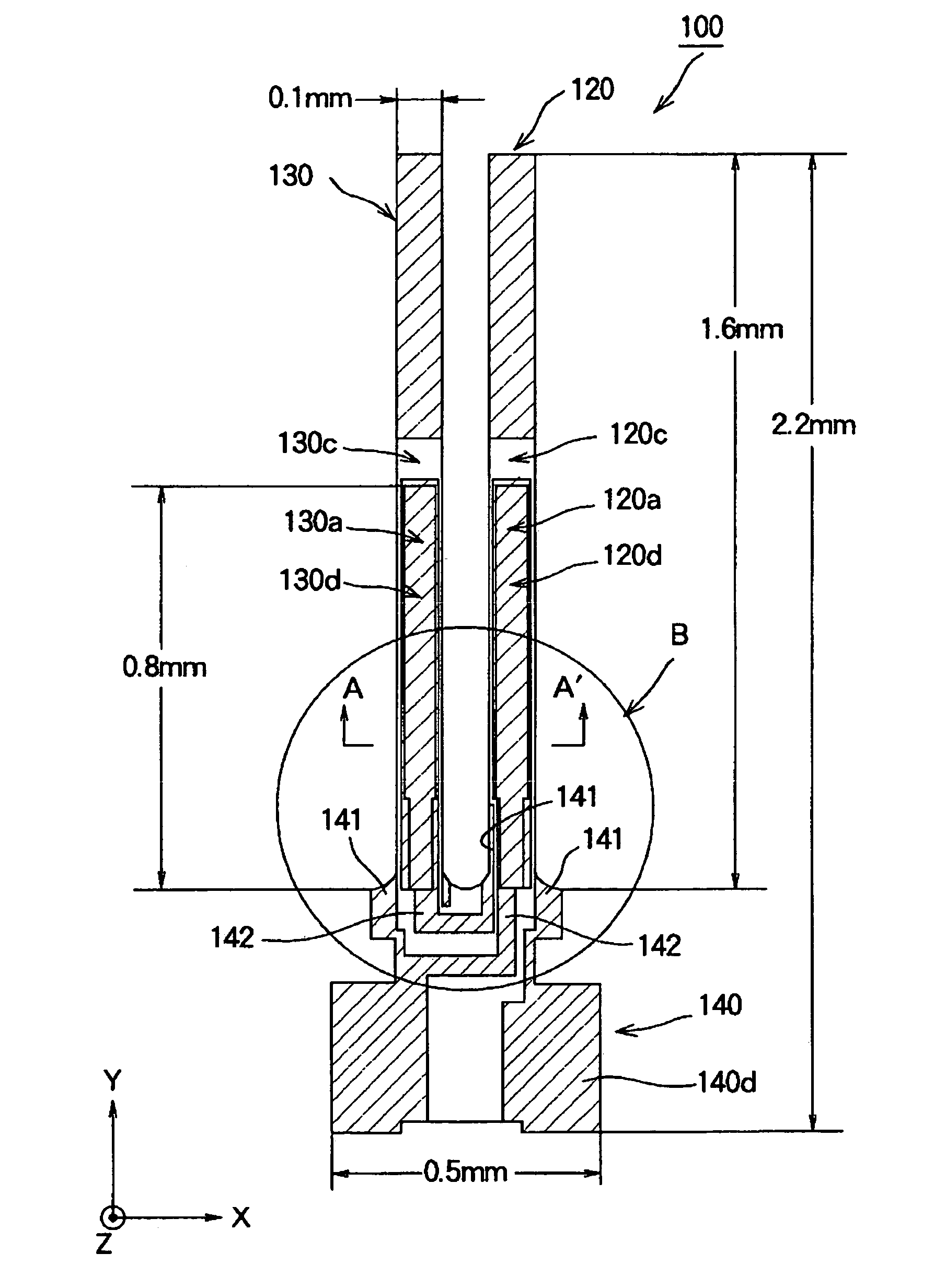
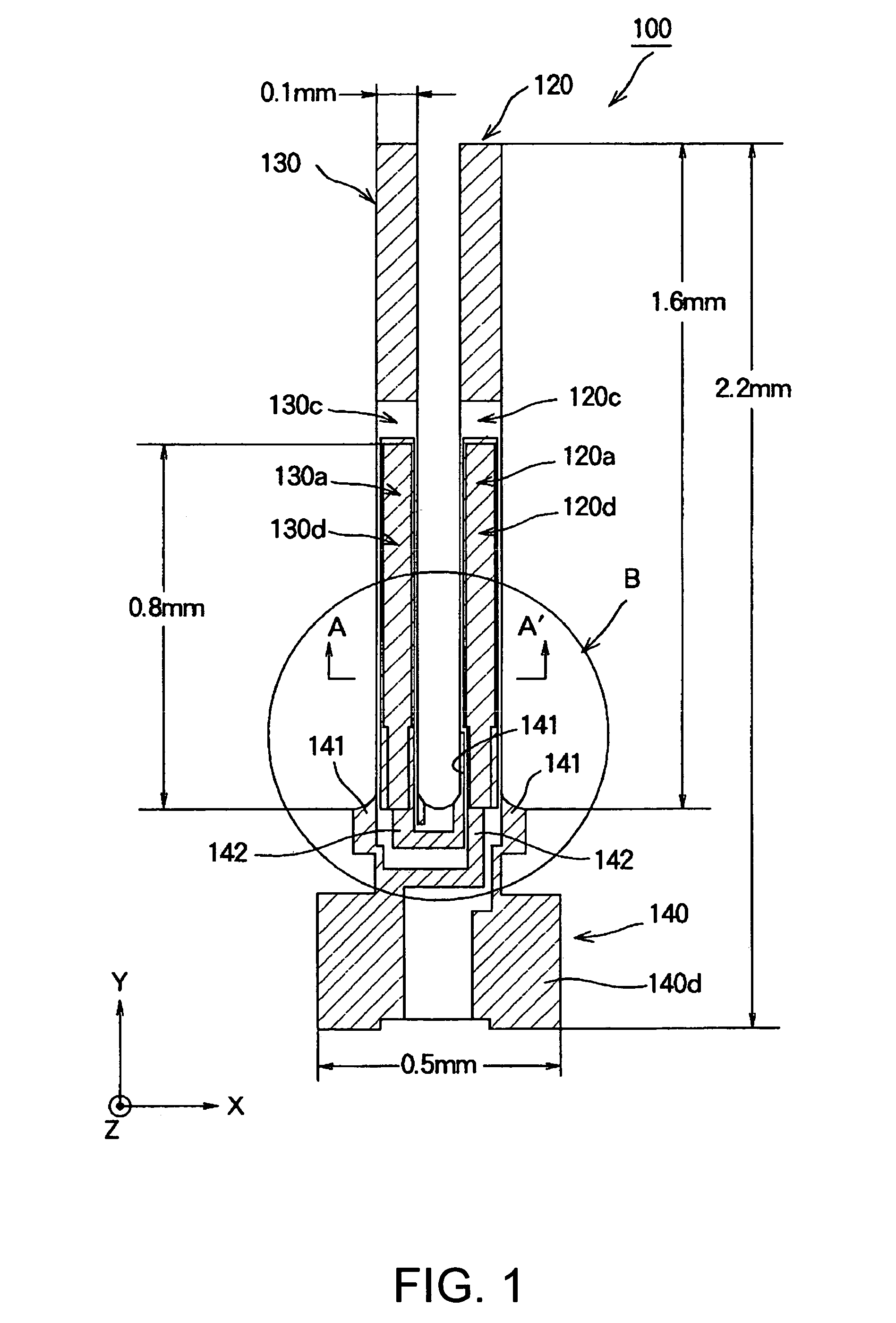
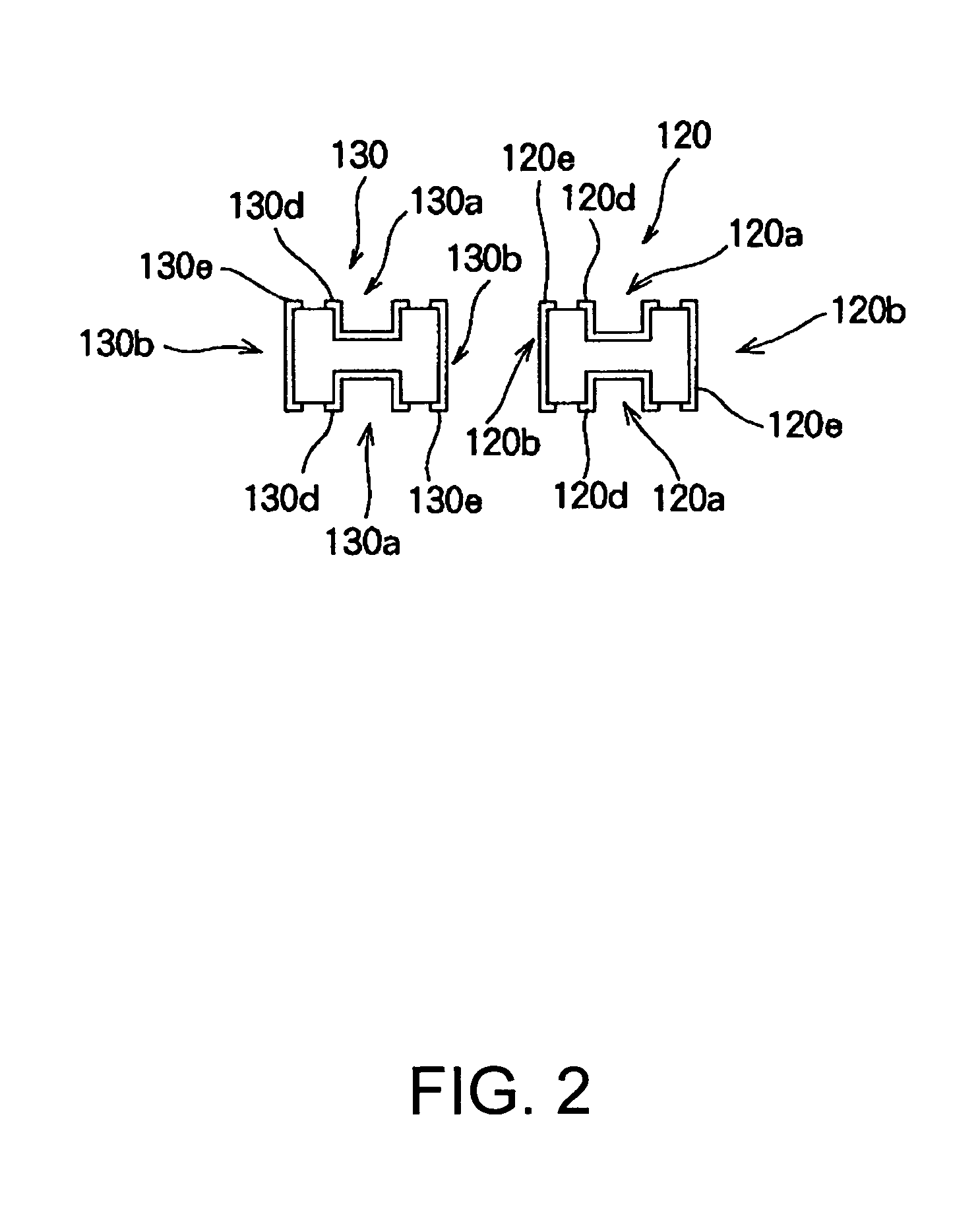
[0057]FIG. 1 is a schematic diagram showing a substantially H-shaped crystal tuning fork resonator piece 100 that is a resonator piece according to a first embodiment of the invention. The substantially H-shaped crystal tuning fork resonator 100 is formed by being cut out from, for example, a monocrystal of crystal and processed into a tuning fork. In this case, the piece is cut out from a monocrystal of crystal so that the X axis shown in FIG. 1 is the electrical axis, the Y axis is the mechanical axis and the Z axis is the optical axis. Because the electrical axis is disposed in the X-axis direction in this manner, the ...


PUM


Abstract

The invention provides a resonator piece, a resonator, an oscillator and an electronic device that can prevent in advance defects from arising in the electrodes and whose frequency characteristics of the resonator piece and CI value are stable. The resonator piece can include a base portion in which a base portion electrode portion is formed, resonating arm portions, groove portions including groove electrode portions, side surface electrode portions, groove electrode-use connection electrode portions, and side surface electrode-use connection electrode portions 141. The width of the base portion side of openings of the groove portions is formed narrower than the width of other portions, with connection electrode disposition portions for disposing the groove electrode-use connection electrode portions or the side surface electrode-use connection electrode portions being formed near the narrowly formed openings of the groove portions, and the shapes of the openings of the groove portions are formed so as to be substantially symmetrical with respect to hypothetical lines disposed along the longitudinal direction at width-direction centers of the groove portions.

Description

BACKGROUND OF THE INVENTION[0001]1. Field of Invention[0002]The present invention relates to a resonator piece comprising, for example, crystal, a resonator including the resonator piece, an oscillator disposed with the resonator, and an electronic device.[0003]2. Description of Related Art[0004]Conventionally, a crystal tuning fork resonator piece, which is, for example, a resonator piece, is configured as shown, for example, in FIG. 9. The crystal tuning fork resonator piece 10 includes a base portion 11 and two arm portions 12 and 13 that are formed so as to project from the base portion 11. Additionally, grooves 12a and 13a are disposed in the two arm portions 12 and 13. The grooves 12a and 13a are similarly disposed on back surfaces of the arm portions 12 and 13 that are not shown in FIG. 9.[0005]For this reason, as shown in FIG. 10, which is a cross-sectional view along E–E′ of FIG. 9, the arm portions 12 and13 are formed so that the cross-sectional shapes thereof have substan...

Claims


Application Information

Patent Timeline
IPC IPC(8): H03H9/21H01L41/047H03B5/32H03H9/02H03H9/05H03H9/10H03H9/19
CPCH03H9/21
Inventor TANAYA, HIDEOKITAMURA, FUMITAKA
Owner SEIKO EPSON CORP
Why Eureka
Try Eureka