Emergency vehicle control system traffic loop preemption

a technology for emergency vehicles and traffic loops, applied in the direction of traffic signals, instruments, traffic detection, etc., can solve the problems of early bias preemption, loose margins for motorists, etc., and achieve the effect of high reliability

Inactive Publication Date: 2006-09-26
CALIFORNIA INST OF TECH
View PDF63 Cites 39 Cited by
  • Summary
  • Abstract
  • Description
  • Claims
  • Application Information

AI Technical Summary

Benefits of technology

[0026]Transceiver power can be set near OSHA's maximum allowable level in order to achieve higher reliability. In order to distinguish transponder response from the transceiver excitation, two separate frequencies are used. These frequencies which are somewhat constrained by the FCC's allocation of the band usage is chosen with the goal of miniaturization of the transponder—the higher the frequency, the smaller the conformal antenna and transponder. Additionally the transceiver / transmission frequency must be set high enough to insure several redundant responses when the detected vehicle is over the traffic loop antenna. Transponder system efficiency is determined by the interaction of the conformal antenna, the harmonic generator, and the embedded digital circuit. Transponder system efficiency is also moderated by the effectiveness of the coupling between the existing traffic loop antenna in the road (which has been designed for a different application) and the transponder antenna.

Problems solved by technology

Since the system is aware of the road system (using an on-board map-matching approach), it is discrete positioning problem (there are a limited subset of solutions to the problem).
Even if a vehicle's position on the correct street is off by 200+ feet in either direction, motorist's “lack of awareness” allow loose margins and early-bias preemption.

Method used


Image

  • Emergency vehicle control system traffic loop preemption
  • Emergency vehicle control system traffic loop preemption
  • Emergency vehicle control system traffic loop preemption

Examples


Embodiment Construction

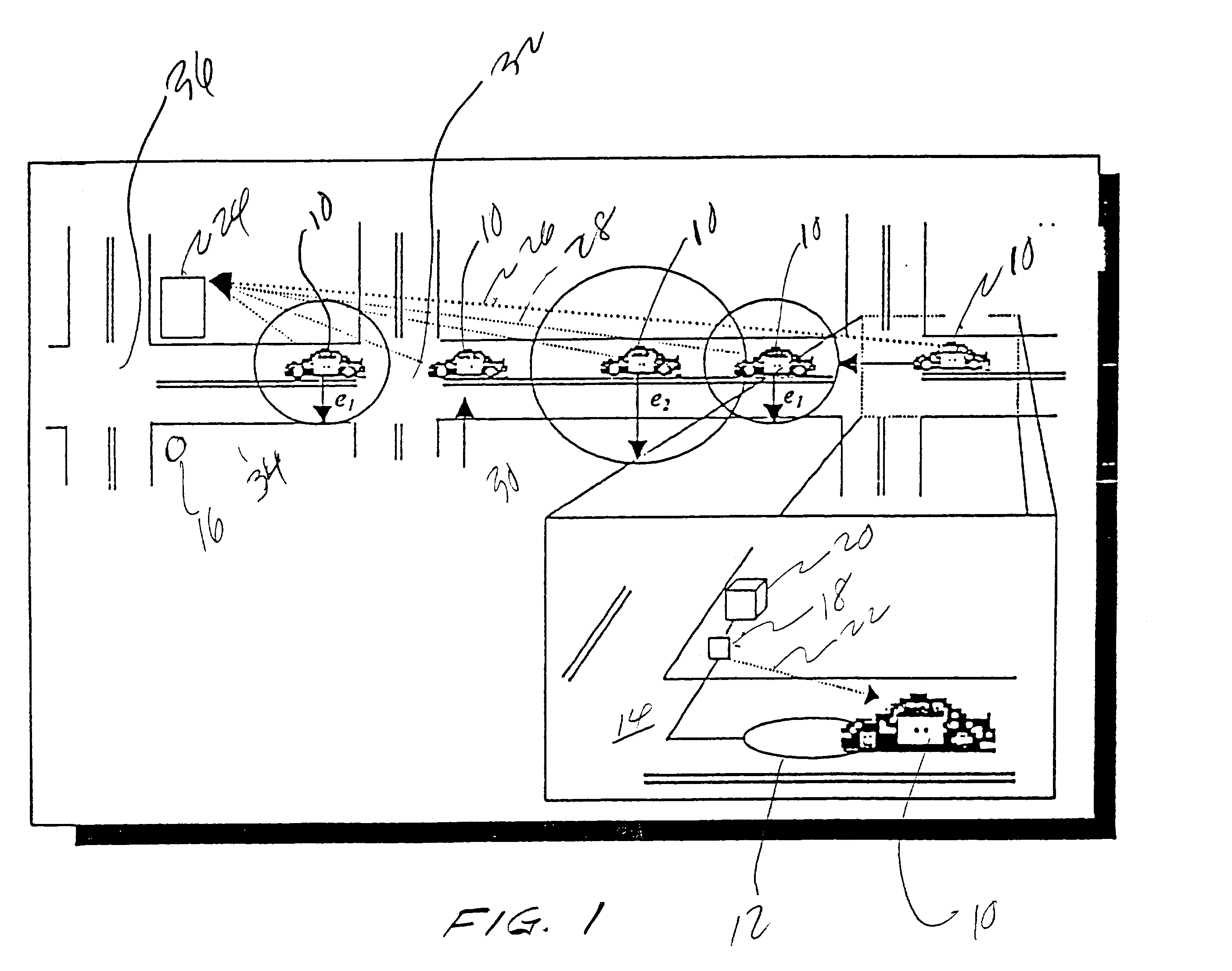
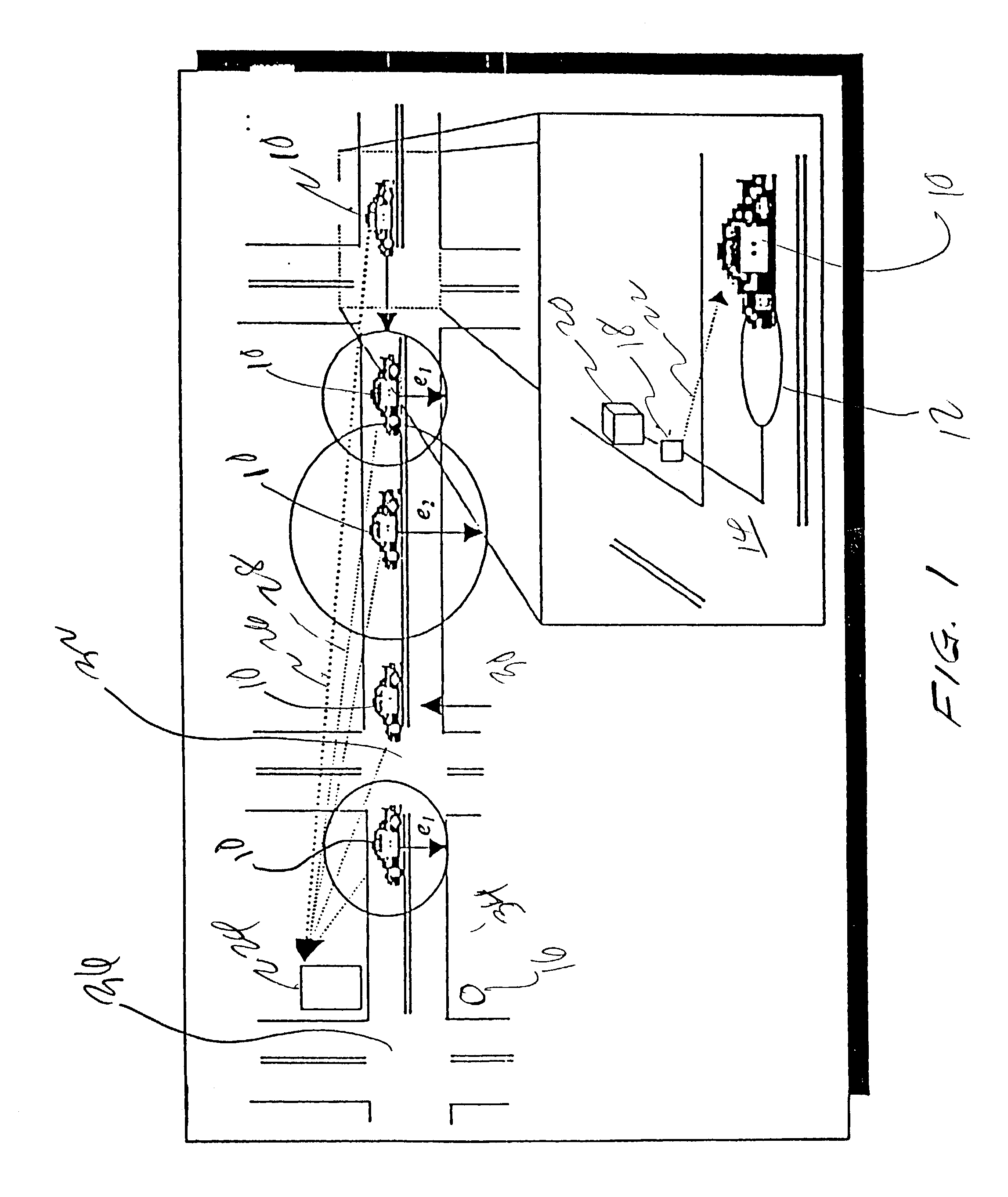
[0037]A “car-active” traffic loop preemption using a pass-through (transmitter to normal behavior of the traffic loop) element between the traffic loop and the traffic loop control box according to the invention is illustrated in FIG. 1. This traffic loop preemption system is designed for use with the emergency vehicle warning and traffic control system such as that shown in U.S. Pat. Nos. 4,704,610 and 4,775,865 of Michael R. Smith et al issued Nov. 3, 1987 and Oct. 4, 1988, respectively and incorporated herein by reference. The traffic light preemption system disclosed herein can be used with systems disclosed there, GPS systems, or as an adjunct to any of the systems available.

[0038]As shown in FIG. 1, when a vehicle 10 travels over inductive traffic loop 12 embedded in pavement 14 of a roadway, vehicle 10 will be detected. Inductive loop 12 also activates a pass-through element resulting in RF transmission of a tag including position (in the form of latitude / longitude and direct...


PUM


Abstract

An emergency vehicle traffic signal preemption system using existing inductive traffic loops that is either “car-active” or “car-passive”. In the “car-active” system, a passive element having position information transmits an ID tag and the position information to a transceiver in the vehicle when an emergency vehicle is detected by the existing inductive traffic loop. In the “car-passive” system, a transceiver at the intersection is activated to send an excitation signal to a transponder on the emergency vehicle. The transponder responds with the emergency vehicle ID. The transceiver in the vehicle in the “car-active” system or the transceiver at the intersection in the “car-passive” system, transmit position information to the traffic controller to preempt operation of the traffic signals.

Description

[0001]Priority of U.S. Provisional Application Ser. No. 60 / 371,037 filed Apr. 9, 2002 is hereby claimed.BACKGROUND OF THE INVENTION[0002]1. Field of the Invention[0003]This invention relates to emergency vehicle control systems for providing warnings of approaching emergency vehicles at intersections and more particularly relates to an emergency vehicle control system that utilizes traffic loop for preemption of traffic signals at an intersection.[0004]2. Background Information[0005]Using existing technology current traffic loops are normally used to detect the presence of cars at an intersection. These traffic loop detectors activate and control the operation of traffic lights at intersections according to the approach of vehicles.[0006]In the past decade, several approaches have been taken to provide traffic signal preemption for emergency vehicles. Existing systems use strobe lights to activate optical receivers at an intersection. Other systems use noise pattern recognition to p...

Claims


Application Information

Patent Timeline
Patent Type & Authority Patents(United States)
IPC IPC(8): G08G1/07
CPCG08G1/087G08G1/042
Inventor BACHELDER, AARON D.FOSTER, CONRAD F.
Owner CALIFORNIA INST OF TECH
Why Eureka
Try Eureka