Force feedback devices using fluid braking

a technology of force feedback and feedback device, which is applied in the field of computer device interface, can solve the problems of high cost, large size and weight, and high cost of passive actuator, and achieve the effects of low cost, high output force and maintaining inherent safety

Inactive Publication Date: 2006-09-26
IMMERSION CORPORATION
View PDF277 Cites 147 Cited by
  • Summary
  • Abstract
  • Description
  • Claims
  • Application Information

AI Technical Summary

Benefits of technology

[0007]The present invention provides a number of embodiments for a force feedback interface device that uses an efficient and small-sized fluid viscosity-controlled brake that outputs high forces at low cost while maintaining inherent safety.
[0009]Several embodiments of the invention can be implemented. For example, a magnetorheological fluid can be suspended in a sponge, such as available from Lord Corporation, which includes an absorbent matrix material, allowing different resistances to be controlled. The sponge can contact a surface that is coupled to the manipulandum, where the surface can be part of a disk or plate. Other embodiments may provide pistons in the fluid. The manipulandum can be moved in rotary or linear degrees of freedom such that the brake can be a rotary or linear brake. The brake can also include a U-shaped member, where an element is coupled to a prong of the U-shaped member and the coil is wound about a central portion of the U-shaped member. Multiple sponges or other such elements can be provided for increased resistive control.
[0011]The present invention provides compact, low-cost, and light weight embodiments for interface devices providing braking forces to an interface device. The controlled viscosity brake used in the present invention provides high-magnitude braking forces and is well-suited to small, inexpensive haptic feedback devices, allowing the interface device of the present invention to be used in mass-produced consumer devices.

Problems solved by technology

However, disadvantages of active actuators include instability: the actuators can settle into a feedback loop in which oscillating forces are output on the manipulandum, for example.
Other disadvantages of active actuators include a high cost, and large size and weight.
However, standard passive actuators can still be expensive for lower-cost devices and can still add significant weight to an interface device.

Method used


Image

  • Force feedback devices using fluid braking
  • Force feedback devices using fluid braking
  • Force feedback devices using fluid braking

Examples


first embodiment

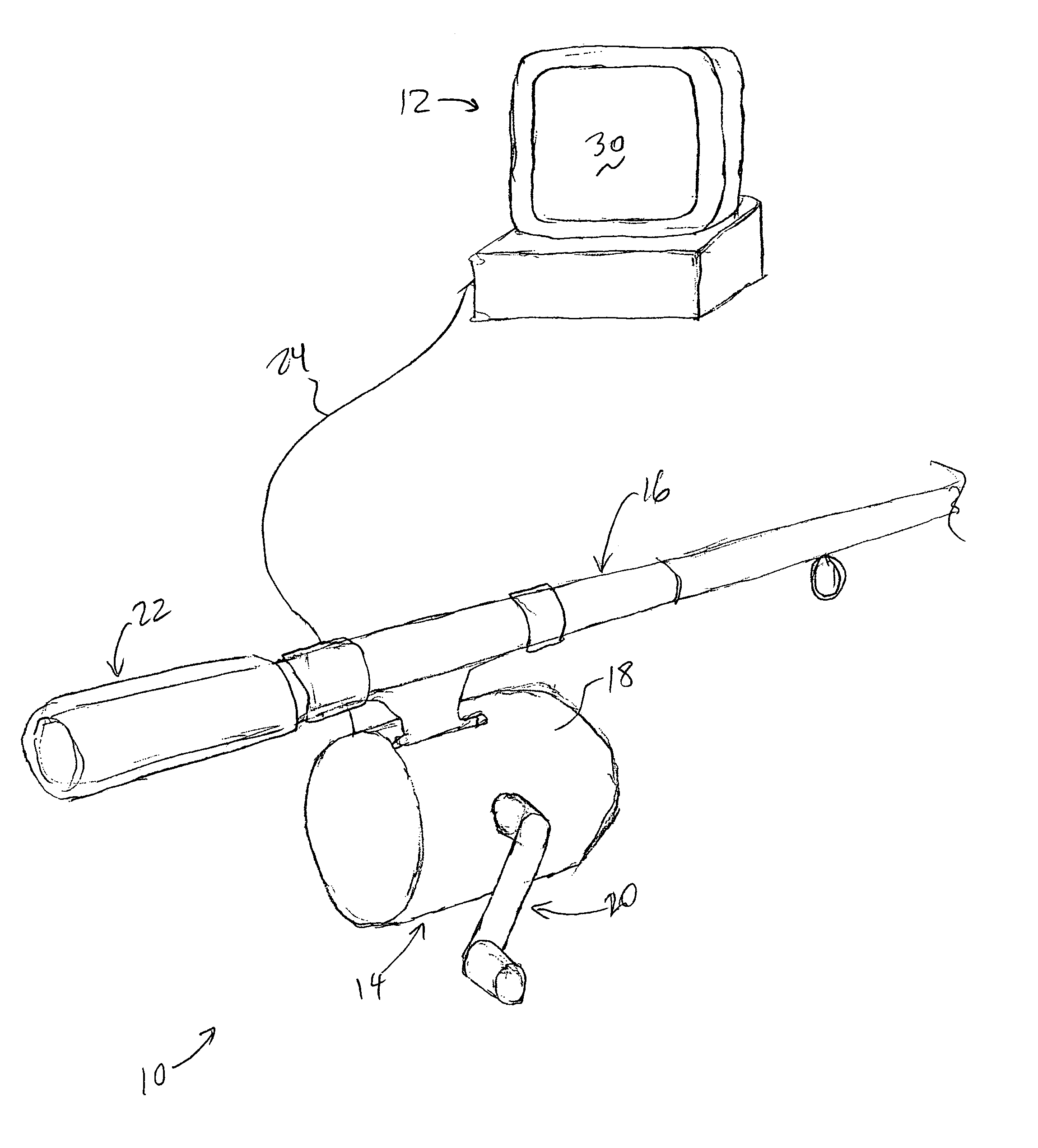
[0020]FIG. 1 is a perspective view of a force feedback interface device 10 of the present invention, in which a fishing game or simulator is implemented. The device 10 is used for interfacing a user with a computer generated environment implemented by a host computer 12.

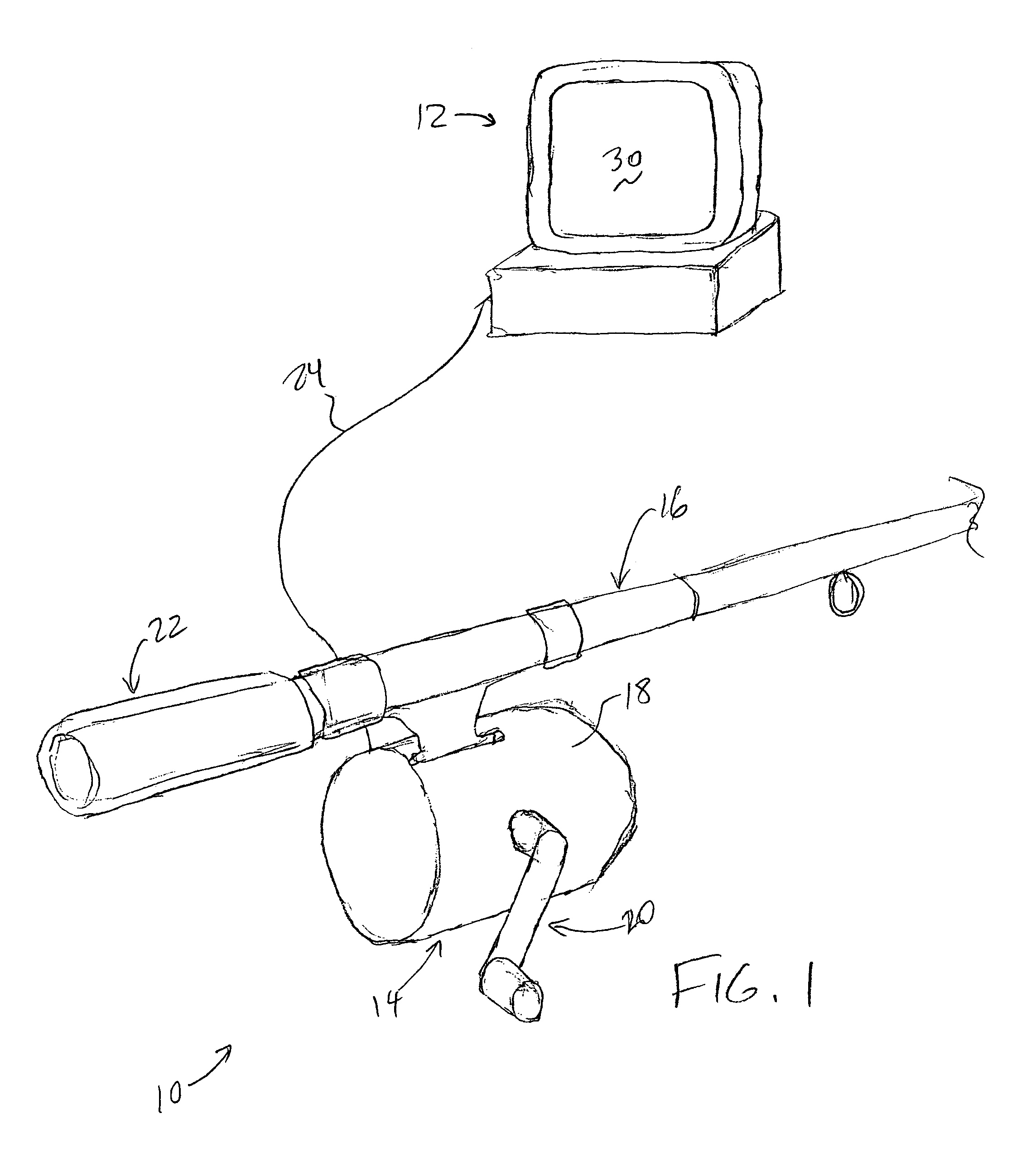
[0021]Interface device 10 of the described embodiment is in the form of a fishing rod and reel, of similar shape and size to rods and reels used by fisherman, and includes a reel unit 14 and a rod 16. Reel unit 14 of the interface device 10 can be shaped and sized similarly to a reel used on a standard fishing rod, and includes a reel housing 16 and a reel crank arm 18. Reel housing 16 encloses mechanisms for reading the position of the reel crank 18 and providing haptic feedback on the reel crank 18, as described in greater detail below with respect to FIG. 2. Reel crank arm 18 can be rotated by the user in a rotary degree of freedom similar to a crank arm on a standard fishing reel. A sensor signal is preferably pr...

second embodiment

[0041]FIG. 3 is a perspective view of the present invention. Interface device 10′ is a bicycle simulation device that can be used to simulate riding a bicycle, similar to a bicycle exercise machine or the like. A stationary frame 80 rests on a ground surface and provides a structure of a similar height to a bicycle. A seat 82 is coupled to the frame on which the user sits during operation of the device 10′. Handlebars 84 are rotatably coupled to the frame 80 and are grasped by the user's hands during operation of the device and may be rotated to simulate turning the bicycle. Pedal assembly 86 is rotatably coupled to the frame 80 and supports the user's feet during operation. The pedal assembly 86 includes pedal arms 88 and pedals 90, each pedal 90 rotatably coupled to an associated pedal arm 88. The pedal arms 88 are preferably rigidly coupled to each other, where the second pedal arm is oriented 180 degrees from the first pedal arm. The pedal arms 88 can be rotated in a rotary degr...

embodiment 120

[0055]FIG. 5 is a perspective view of another embodiment 120 of an interface device of the present invention including a magnetorheological brake. Embodiment 120 includes a two-degree of freedom cylindrical controller that can be used to provide input control signals to a computer or other electronic device, e.g. to control the movement of a cursor in a graphical user interface displayed by a host computer 12. A cylinder 122 may be rotated about an axis C and translated parallel to the axis C by the user. The outer surface of the cylinder 122 can include annular and longitudinal grooves 124 which intersect each other. Two pinions 126 positioned at right angles with respect to each other mesh with the grooves 124 so that when the cylinder is rotated, one pinion 126a rotates, and when the cylinder is translated, the other pinion 126b rotates. A metal disk 128 is connected to each pinion 126 by a rotating shaft 130, and an magnetorheological brake 132 as described in detail in FIG. 2 p...


PUM


Abstract

A haptic feedback device including a fluid viscosity-controlled brake that outputs high forces to the device user at low cost while maintaining inherent safety. An interface device includes a manipulandum physically contacted by the user. A sensor senses a position of the manipulandum and outputs a sensor signal. The interface device also includes a brake including a field-controlled fluid having a viscosity that can be controlled by controlling an electric current in a coil, where a resistive force or drag on the manipulandum is controlled by controlling the fluid's viscosity. The fluid can be an electrorheological fluid controlled by an electric field or a magnetorheological fluid controlled by a magnetic field. In one preferred embodiment, the resistive force is controlled by adjusting a degree of contact of the brake with the manipulandum based on the fluid's viscosity. Disclosed embodiments include fishing devices, bicycle simulators, and control knobs.

Description

CROSS REFERENCE TO RELATED APPLICATIONS[0001]This application is a continuation-in-part of the following applications:[0002]U.S. patent application Ser. No. 09 / 028,082, now U.S. Pat. No. 6,486,872, filed Feb. 23, 1998, which is a continuation of U.S. patent application Ser. No. 08 / 489,068, now U.S. Pat. No. 5,721,566, filed Jun. 9, 1995, and U.S. patent application Ser. No. 08 / 965,720, filed Nov. 7, 1997, now U.S. Pat. No. 6,166,723 each of which are incorporated by reference in their entirety. This application also claims priority to U.S. Provisional Application No. 60 / 128,975, filed Apr. 12, 1999 on behalf of L. Rosenberg; which is incorporated herein by reference in its entirety.BACKGROUND OF THE INVENTION[0003]The present invention relates generally to the interfacing with computer devices by a user, and more particularly to devices used to provide input to computer systems and which provide force feedback to the user.[0004]Humans interface with electronic devices in a variety o...

Claims


Application Information

Patent Timeline
Patent Type & Authority Patents(United States)
IPC IPC(8): G09G5/00
CPCA63B21/0057G09B9/00G09B19/00G06F3/016A63B23/14A63B69/00A63B22/0605
Inventor ROSENBERG, LOUIS B.SCHENA, BRUCE M.
Owner IMMERSION CORPORATION
Why Eureka
Try Eureka