High power fiber chirped pulse amplification system utilizing telecom-type components

a technology of telecom-type components and high-power fibers, applied in the direction of electromagnetic repeaters, active medium materials, electromagnetic transmission, etc., can solve the problems of little research occurring recently, inconvenient use, and inability to meet the requirements of acousto-optic modulators working at 1550 nanometers, and achieves superior mechanical stability.

Inactive Publication Date: 2006-09-26
IMRA AMERICA
View PDF17 Cites 99 Cited by
  • Summary
  • Abstract
  • Description
  • Claims
  • Application Information

AI Technical Summary

Benefits of technology

[0017]The invention has been made in view of the above circumstances and to overcome the above problems and limitations of the prior art, and provides an erbium fiber (or erbium-ytterbium) based chirped pulse amplification system operating at a wavelength of approximately 1550 nanometers. The use of fiber amplifiers operating in the telecommunications window enables the implementation of telecommunications components and telecommunications compatible assembly procedures with superior mechanical stability.

Problems solved by technology

However, at wavelengths of approximately 1550 nanometers, very little research has occurred recently.
However, at wavelengths around 1550 nanometers, such an acousto-optic modulator is not readily available due to material limitations, especially when the original pulse repetition rate is higher than 20 megahertz.
However, at such a speed, acousto-optic modulators working at 1550 nanometers are either not readily available or very expensive.
In addition, such modulators have high insertion losses.
For example, Brimrose manufactures an AO modulator with acceptable performance at 1550 nanometers, but each modulator costs several thousand dollars.
Such high costs can limit mass production of amplification systems using such AO modulators.
No chirped pulse amplification system, however, has ever used such an electro-optic modulator system.
Although technically sufficient, the coupling element is not suited to mass production, due to the labor-intensive assembly involved.
In addition, the long-term operational stability of the system is usually an issue as well.
Due to the polarization sensitive nature of the LiNbO3 modulator, it can not be used in the same double pass loop with other non-polarization-maintaining fiber components.
This low signal / noise contrast ratio is inadequate for a chirped pulse amplification system, and has to be increased to at least 30 decibels, or higher.

Method used


Image

  • High power fiber chirped pulse amplification system utilizing telecom-type components
  • High power fiber chirped pulse amplification system utilizing telecom-type components
  • High power fiber chirped pulse amplification system utilizing telecom-type components

Examples


Embodiment Construction

[0032]A detailed description of the preferred embodiments of the invention will now be given referring to the accompanying drawings.

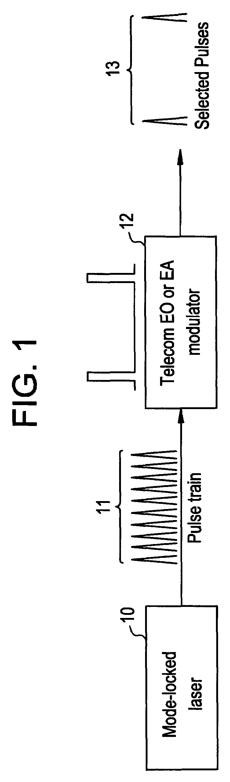
[0033]For chirped pulse amplification systems operating at wavelengths of approximately 1550 nanometers, acousto-optic modulators with fast rise times have limited availability, due to lack of appropriate materials. However, the telecommunications electro-optic modulators and electro-absorption modulators provide an alternative solution. Such modulators, however, have not been used in a chirped pulse amplification system for the purpose of pulse selection. Referring to FIG. 1, a chirped pulse amplification system is illustrated. A mode-locked laser 10 outputs a pulse stream 11, which is input into a modulator 12. The modulator 12 then modulates the incoming pulse stream 11, and outputs the selected pulses 13. The modulator 12 can be a LiNbO3 electro-optic modulator or an electro-absorption modulator.

[0034]In the present invention, a LiNbO3 modulator is ...


PUM


Abstract

An erbium fiber (or erbium-ytterbium) based chirped pulse amplification system is illustrated. The use of fiber amplifiers operating in the telecommunications window enables the implementation of telecommunications components and telecommunications compatible assembly procedures with superior mechanical stability.

Description

BACKGROUND OF THE INVENTION[0001]1. Technical Field of the Invention[0002]The present invention relates to the chirped pulse amplification of an ultrashort optical pulse, and more specifically, to chirped pulse amplification using commercial telecommunications components, such as a LiNbO3 modulator for a pulse selector. The present invention further relates to techniques for integration of components together to avoid free space alignment, which results in a more simple assembly process and improved mechanical stability.[0003]2. Description of the Related Art[0004]The following references provide useful background information on the indicated topics, all of which relate to the invention, and are incorporated herein by reference:[0005]A. Galvanauskas and M. E. Fermann, 13-W Average Power Ultrafast Fiber Laser, Conference on Lasers and Electro-Optics 2000, San Francisco, Calif., May 7–12, 2000, post deadline paper CPD3.[0006]Y. Jaouen, M. Le Flohic, E. Olmedo and G. Kulscar, 35 kW Sub...

Claims


Application Information

Patent Timeline
Patent Type & Authority Patents(United States)
IPC IPC(8): H01S3/00H01S4/00H01SH01S3/067H01S3/094H01S3/0941H01S3/16H01S3/23H04B10/29
CPCH01S3/0057H01S3/06754H01S3/2333H01S3/0085H01S3/06725H01S3/0941H01S3/1608H01S3/1618H01S3/2316H01S3/094003
Inventor GU, XINHUAUEHARA, YUZURUHARTER, DONALD
Owner IMRA AMERICA
Why Eureka
Try Eureka