[0017]The present invention has for its object to provide an image coding apparatus that transfers an equivalent amount of data to / from a memory also when plural coded data are outputted from one image input, and can be obtained at a lower
system cost with little increase in the circuit scale or
processing time.
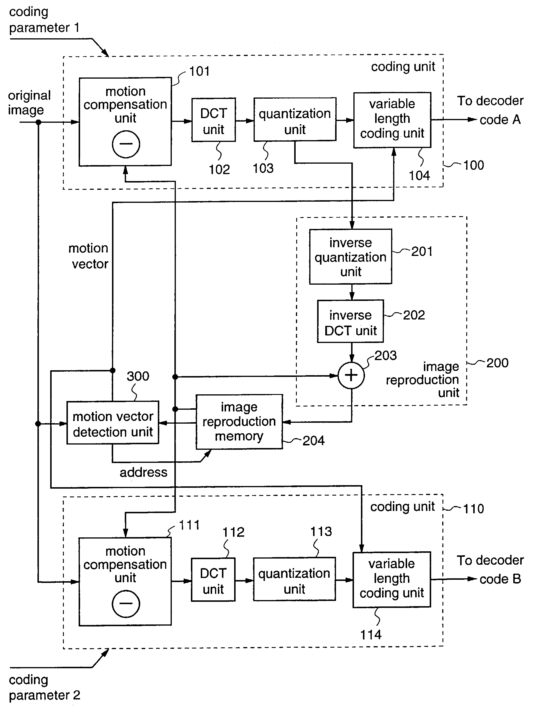
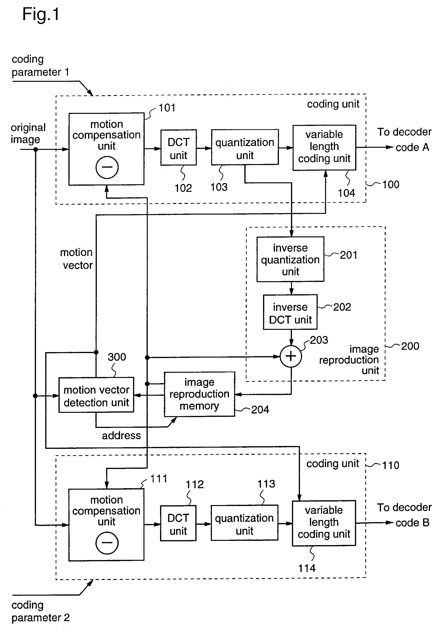
[0019]According to a 1st aspect of the present invention, there is provided an image coding apparatus that outputs plural codes for one coding target image, utilizing motion compensation inter-frame prediction including: a motion vector detection unit for dividing the coding target image into predetermined blocks and extracting a block in a search image, having a highest correlation with each of the predetermined blocks, thereby to detect a first motion vector for each of the predetermined blocks; N (N is an integer equal to two or larger than two) pieces of coding units for coding the first motion vector as well as performing motion compensation inter-frame prediction using an image in a position indicated by the first motion vector in the search image and the coding target image, in accordance with coding parameters which are given from outside, thereby to generate coded data; an image reproduction unit for reconstructing an image using coded data which is outputted from one of the coding units; and an image reproduction memory for storing the image reconstructed by the image reproduction unit, as a search image to be supplied to the motion vector detection unit, and the N pieces of coding units
encode the coding target image in accordance with the coding parameters which are given to the respective coding units, and output the respective coded data. Therefore, in the image coding apparatus that generates plural kinds of coded data, the coding units can share the image reproduction unit, the image reproduction memory, and the motion vector detection unit, to reduce the circuit scale. Further, this image coding apparatus requires only one set of processes by the motion vector detection unit and the image reproduction unit, so that the processing time can be reduced. In addition, the image reproduction unit reconstructs an image using coded data which is outputted from one of the coding units, whereby the amount of data transferred from the image reproduction unit to the image reproduction memory in the case of generating plural kinds of coded data can be made equivalent to the amount of transferred data in the case of generating one kind of coded data, and accordingly an image coding apparatus having a lower
system cost is realized without increasing the circuit scale, the number of data pins, and the processing time.
[0020]According to a 2nd aspect of the present invention, there is provided an image coding apparatus that outputs plural codes for one coding target image, utilizing motion compensation inter-frame prediction including: a motion vector detection unit for dividing the coding target image into predetermined blocks and extracting a block in a search image, having a highest correlation with each of the predetermined blocks, thereby to detect a first motion vector for each of the predetermined blocks; a first memory for storing the coding target image; a coding unit for coding the first motion vector as well as performing motion compensation inter-frame prediction using an image in a position indicated by the first motion vector in the search image and the coding target image, in accordance with plural coding parameters which are supplied from outside to the one coding target image, thereby successively generating coded data corresponding to each of the plural coding parameters; an image reproduction unit for reconstructing an image employing one of the coded data which are generated by the coding unit; and a second memory for storing the image reconstructed by the image reproduction unit as a search image that is supplied to the motion vector detection unit. Therefore, plural kinds of coded data can be generated without providing plural coding units corresponding to the plural coding parameters, respectively, so that the entire circuit scale of the image coding apparatus can be reduced. Further, the image reproduction unit reconstructs an image employing one of the coded data which are generated by the coding unit, whereby also in the case of outputting plural kinds of coded data with respect to one image input, the amount of data transferred from the image reproduction unit to the image reproduction memory can be made equivalent to that in the case of generating one coded data, and accordingly an image coding apparatus having a lower system cost can be provided without increasing the circuit scale, the number of data pins, or the processing time.
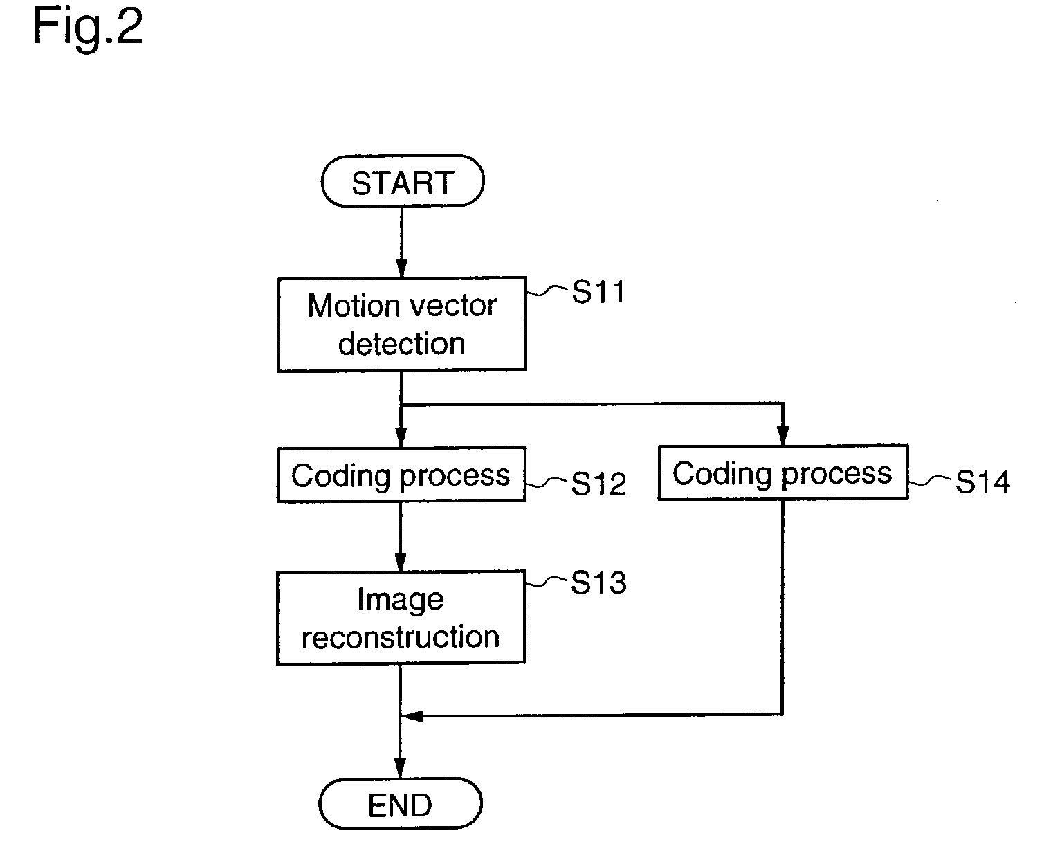
[0021]According to a 3rd aspect of the present invention, there is provided an image coding method for outputting plural codes for one coding target image, utilizing motion compensation inter-frame prediction including: a motion vector detection step of dividing the coding target image into predetermined blocks and extracting a block in a search image, having a highest correlation with each of the predetermined blocks, thereby to detect a first motion vector for each of the predetermined blocks; a first coding step of coding the first motion vector as well as performing motion compensation inter-frame prediction using an image in a position indicated by the first motion vector in the search image and the coding target image, in accordance with a coding parameter that is given from outside, thereby to generate coded data; an image reproduction step of reconstructing an image using the coded data that is generated in the first coding step; a reproduced
image storage step of storing the image reconstructed in the image reproduction step, as a search image to be employed in the motion vector detection step; and a second coding step of coding the first motion vector as well as performing motion compensation inter-frame prediction using the image in the position indicated by the first motion vector in the search image and the coding target image, in accordance with the coding parameter given from the outside, thereby to generate coded data, and then the first coding step and said second coding step are carried out in parallel. Therefore, also when plural kinds of coded data are to be generated, the motion vector detection process in the motion vector detection step and the image reconstruction process in the image reproduction step are carried out in one process, so that the processing time can be reduced. Further, the image reconstruction in the image reproduction step is performed using the coded data that is generated in the first coding step, whereby also in the case of generating plural kinds of coded data, the amount of transferred data corresponding to the image reconstructed in the image reproduction step can be made equivalent to that in the case of outputting one kind of coded data, and accordingly an image coding method having a lower operation cost is provided without increasing the processing time.
[0022]According to a 4th aspect of the present invention, there is provided an image coding method for outputting plural codes for one coding target image, utilizing motion compensation inter-frame prediction including: a coding target
image storage step of storing the coding target image; a motion vector detection step of dividing the coding target image into predetermined blocks and extracting a block in a search image, having a highest correlation with each of the predetermined blocks, thereby to detect a first motion vector for each of the predetermined blocks; a coding step of coding the first motion vector as well as performing motion compensation inter-frame prediction using an image in a position indicated by the first motion vector in the search image and the coding target image, in accordance with plural coding parameters supplied from outside for the one coding target image, thereby successively generating coded data corresponding to each of the plural coding parameters; an image reproduction step of reconstructing an image using one coded data that is generated in the coding step; and a search
image storage step of storing the image reconstructed in the image reproduction step as a search image that is used in the motion vector detection step. Therefore, also when plural kinds of coded data are to be generated, the motion vector detection in the motion vector detection step and the image reconstruction in the image reproduction step can be performed in one process, so that the processing time can be reduced. Further, the image reconstruction in the image reproduction step is performed using one coded data that is generated in the coding step, whereby also in the case of generating plural kinds of coded data, the amount of transferred data corresponding to the image that is reconstructed in the image reproduction step can be made equivalent to that in the case of outputting one coded data, and accordingly an image coding method having a lower operation cost can be provided without increasing the processing time.

