
Compressor

a compression and compression technology, applied in the field of compression, can solve the problems of increasing vibration and torque fluctuation, high cost, and enlarged difference between high and low pressure, and achieve the effect of preventing efficiency deterioration

Inactive Publication Date: 2006-10-03
SANYO ELECTRIC CO LTD
View PDF10 Cites 7 Cited by
  • Summary
  • Abstract
  • Description
  • Claims
  • Application Information

AI Technical Summary

Benefits of technology

[0008]The present invention has been made to solve the aforementioned conventional technical problems, and it is an object of the invention to provide an efficient compressor which is simple in structure and small in torque fluctuation.

Problems solved by technology

The rotary compressor has advantages in that a structure is relatively simple and production costs are low, but there is a problem of increases in vibration and torque fluctuation.
In the case of the scroll compressor and the screw compressor, there is a problem of high costs caused by bad workability while torque fluctuation is small.
However, in the case of the structure of the Patent Document 2, because a high pressure chamber and a low pressure chamber are adjacent to each other below and above the swash plate in the entire region of the cylinder, a difference between high and low pressures is enlarged, and refrigerant leakage causes a problem of efficiency deterioration

Method used


Image

  • Compressor
  • Compressor
  • Compressor

Examples


first embodiment

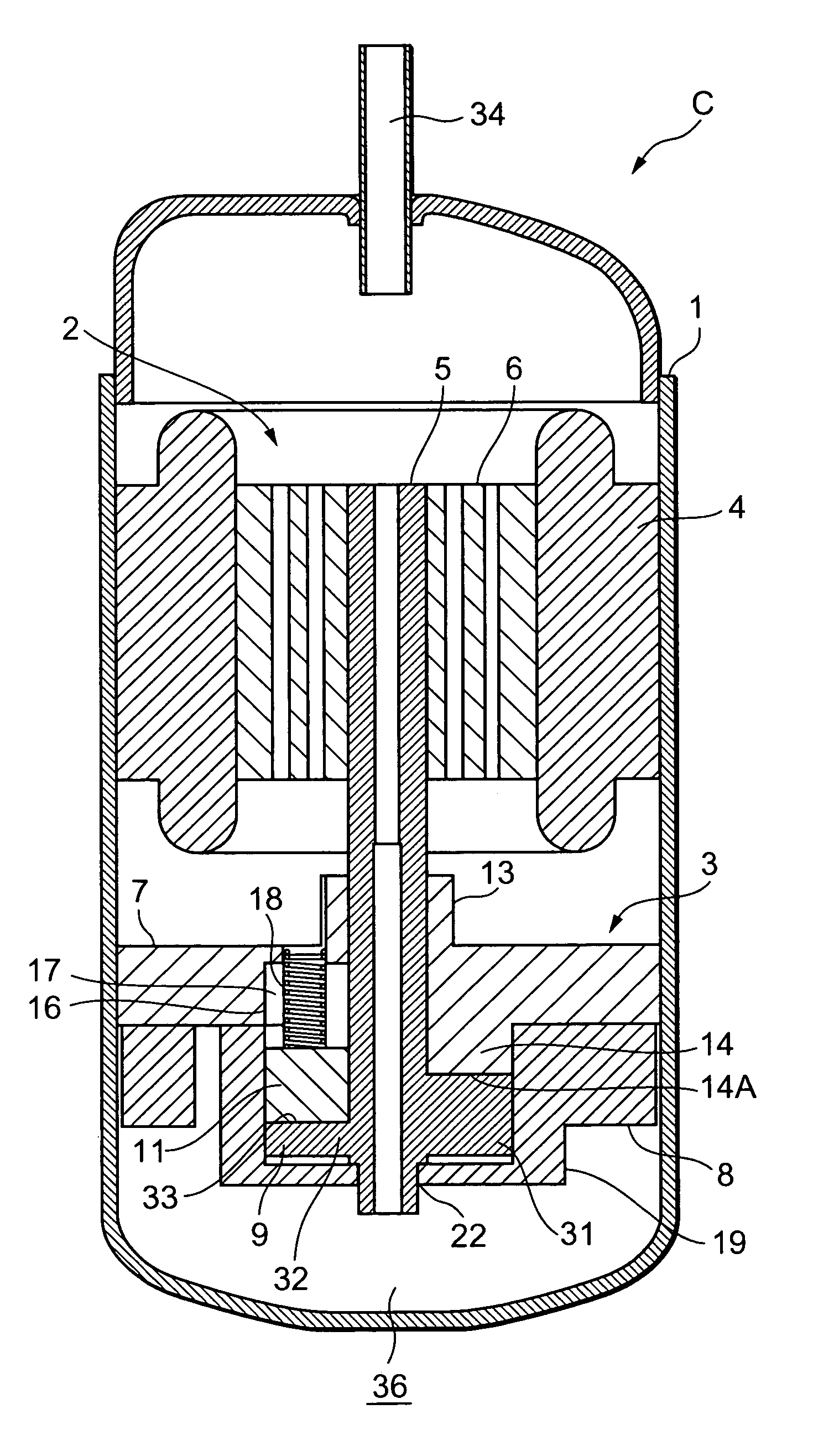
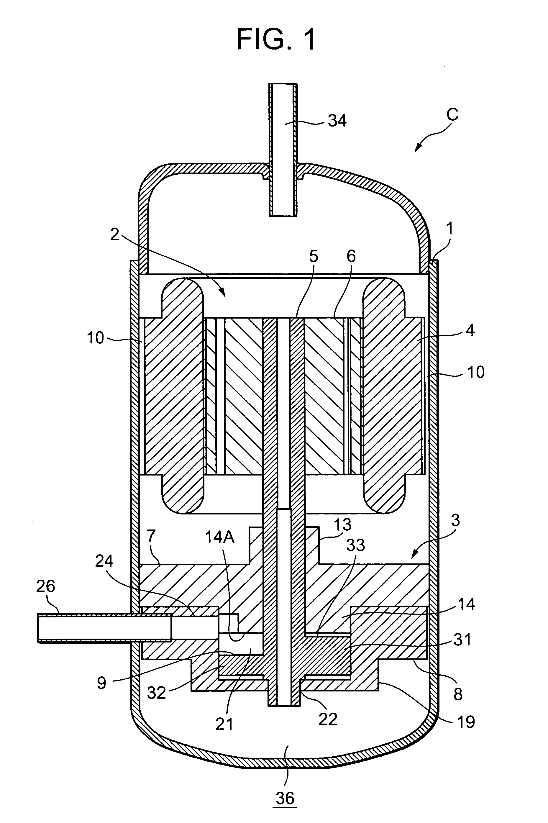
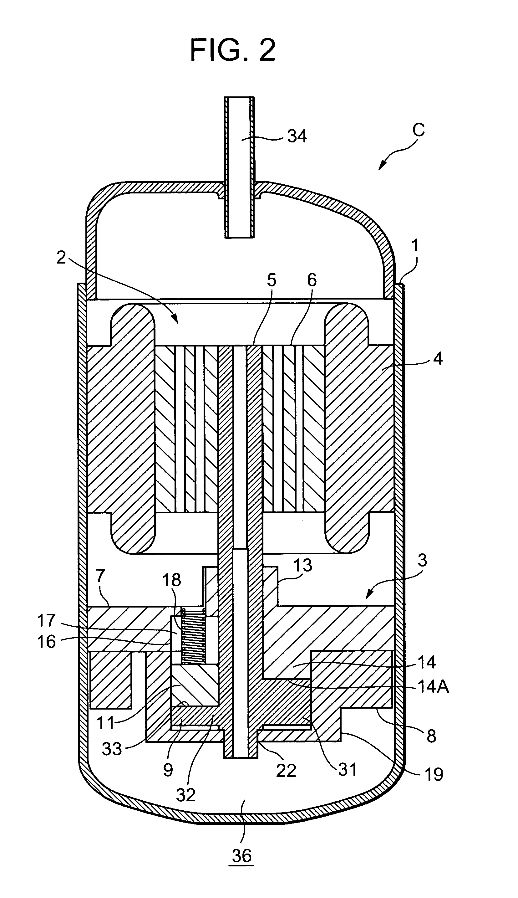
[0085]FIG. 1 is a vertical sectional side view showing the compressor C according to a first embodiment of the present invention, FIG. 2 is another vertical sectional side view, FIG. 3 is a plan sectional view of the compressor C, FIG. 4 is another plan sectional view, FIGS. 5 to 7 are perspective views of a compression element 3 of the compressor C, and FIGS. 8, 9 are side views thereof. Throughout the drawings, a reference numeral 1 denotes a sealed container which receives a driving element 2 in its upper side and a compression element 3 driven by the driving element 2 in its lower side.

[0086]The driving element 2 is an electric motor which is fixed to an inner wall of the sealed container 1 and which comprises a stator 4 having a stator coil wound thereon and a rotor 6 having a rotary shaft 5 in a center inside the stator 4. Incidentally, a clearance 10 is formed between an outer peripheral part of the stator 4 of the driving element 2 and the sealed container 1 to communicate u...

second embodiment

[0101]Next, referring to FIGS. 14 to 24, the compressor C of a second embodiment will be described. FIG. 14 is a vertical sectional side view of the compressor C of the second embodiment, FIG. 15 is another vertical sectional side view, FIGS. 16 to 18 are perspective views of a compression element 3 of the compressor C in this case, FIGS. 19, 20 are side views thereof, FIGS. 21 and 22 are side views of a rotary shaft 5 which includes a compression member 9, FIG. 23 is a bottom view, and FIG. 24 is a perspective view.

[0102]Throughout the drawings, portions denoted by reference numerals similar to those of FIGS. 1 to 13 exhibit identical or similar functions, and thus description thereof will be omitted. In this case, a recess 39 is formed from a bottom surface (other surface) 38 in a portion corresponding to a thick part 31 of the compression member 9. A depth of the recess 39 is formed along a slope of an upper surface 33, and a position corresponding to a top dead center 33A is rec...

third embodiment

[0104]Next, referring to FIGS. 25 to 35, the compressor C of a third embodiment will be described. FIG. 25 is a vertical sectional side view of the compressor C of the second embodiment, FIG. 26 is another vertical sectional side view, FIGS. 27 to 29 are perspective views of a compression element 3 of the compressor C in this case, FIGS. 30, 31 are side views thereof, FIGS. 32 and 33 are side views of a rotary shaft 5 which includes a compression member 9 in this case, FIG. 34 is a bottom view, and FIG. 35 is a perspective view.

[0105]Throughout the drawings, portions denoted by reference numerals similar to those of FIGS. 1 to 24 exhibit identical or similar functions, and thus description thereof will be omitted. A bottom surface (other surface) 38 of the compression member 9 is formed to be a slope directed from the rotary shaft 5 side to a peripheral part in which the peripheral part side rises to approach an upper surface 33 side. Thus, because air resistance during rotation of ...


PUM


Abstract

There is provided an efficient compressor which is simple in structure and small in torque fluctuation. The compressor comprises a compression element which comprises a cylinder having a compression space formed therein, a suction port and a discharge port which communicate with the compression space in the cylinder, a compression member which comprises continuous thick and thin parts, one surface of which inclines, which is arranged in the cylinder to rotate, and which compresses fluids sucked through the suction port and discharges the compressed fluids through the discharge port, and a vane which is arranged between the suction port and the discharge port to abut on one surface of the compression member, and which partitions the compression space of the cylinder into a low pressure chamber and a high pressure chamber.

Description

BACKGROUND OF THE INVENTION[0001]1. Field of the Invention[0002]The present invention relates to a compressor which compresses fluids such as refrigerants or air and discharges the compressed fluids.[0003]2. Description of the Related Art[0004]Conventionally, for example, a refrigerator has employed a system of compressing a refrigerant by using a compressor and circulating the compressed refrigerant in a circuit. As such compressor systems in this case, there are available a rotary compressor called a rotary type compressor (e.g., see Japanese Patent Application Laid-Open No. 5-99172), a scroll compressor and a screw compressor.[0005]The rotary compressor has advantages in that a structure is relatively simple and production costs are low, but there is a problem of increases in vibration and torque fluctuation. In the case of the scroll compressor and the screw compressor, there is a problem of high costs caused by bad workability while torque fluctuation is small.[0006]Thus, there...

Claims


Application Information

Patent Timeline
Patent Type & Authority Patents(United States)
IPC IPC(8): F04C2/344F04C27/00F01C21/08F04C18/34F04C18/356F04C23/00F04C29/00
CPCF01C21/08F01C21/0845F04C23/008F04C27/001F04C18/3568F04C27/005F04C18/356F04C29/00
Inventor OGASAWARA, HIROTSUGUNISHIKAWA, TAKAHIROSUDA, AKIHIROHARA, MASAYUKIOONUKI, MAKOTO
Owner SANYO ELECTRIC CO LTD
Learn More