Heat sink and electromagnetic interference reduction device

a technology of electromagnetic interference and heat sink, which is applied in the field of electric assembly, can solve the problems of high power consumption of electric devices, central processing units in particular, and more heat than can be convected away, and achieve the effects of improving grounding, efficient space, and improving heat convection

Inactive Publication Date: 2006-10-03
ORACLE INT CORP
View PDF60 Cites 8 Cited by
  • Summary
  • Abstract
  • Description
  • Claims
  • Application Information

AI Technical Summary

Benefits of technology

[0009]The present invention relates to an electrical assembly having heat dissipation and EMI reduction features. The electrical assembly includes a heat dissipation device, an electrical device that is capable of emitting heat and EMI, and a circuit board. A first embodiment of the electrical assembly of the invention includes a first embodiment of a heat dissipation device of the invention. The first embodiment of the heat dissipation device has a plurality of fins disposed in matrix orientation that are efficiently spaced from one another and has fins that have a cross sectional shape that is symmetric about two orthogonal axes. The efficient spacing improves heat convection, and the symmetrical cross sectional shape allows for efficient convection in two orthogonal directions. Further, the first embodiment includes a solder ring instead of a compliant member for grounding. The heat dissipation device includes an EMI fence that has connector receiving portions that are offset from a bottom surface of the fence to ensure contact between a bottom surface of the EMI fence and the solder ring. This improves grounding between the heat dissipation device and the circuit board.

Problems solved by technology

Electrical devices, and central processing units in particular, draw high power and produce more heat than can be convected away from the dies of the device.
If the die temperature exceeds acceptable levels, the device will either cease functioning, not operate at acceptable levels, and / or function in an unreliable manner.
In addition, many electrical devices emit electromagnetic interference (EMI) that can adversely affect nearby electronics or electronic communication.
For example, prior art heat dissipation devices that use a matrix of fins incorporate fins that have inefficient dimensions and that are inefficiently spaced for heat conduction and heat convection purposes.
Moreover, many heat dissipation devices incorporate an inefficient cross sectional fin shape, such as an undesirable rectangular shape, that only permits satisfactory heat dissipation when positioned in a first orthogonal orientation.
Thus, these heat dissipation devices cannot adequately dissipate heat when positioned in a second orthogonal orientation.
The thermal interface material used, however, is expensive.
The complaint member, however, adds extra costs.

Method used


Image

  • Heat sink and electromagnetic interference reduction device
  • Heat sink and electromagnetic interference reduction device
  • Heat sink and electromagnetic interference reduction device

Examples


Embodiment Construction

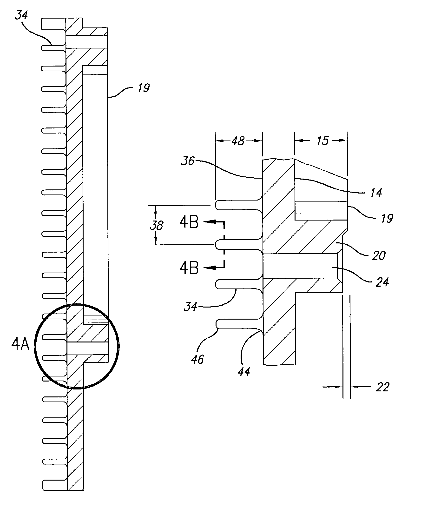
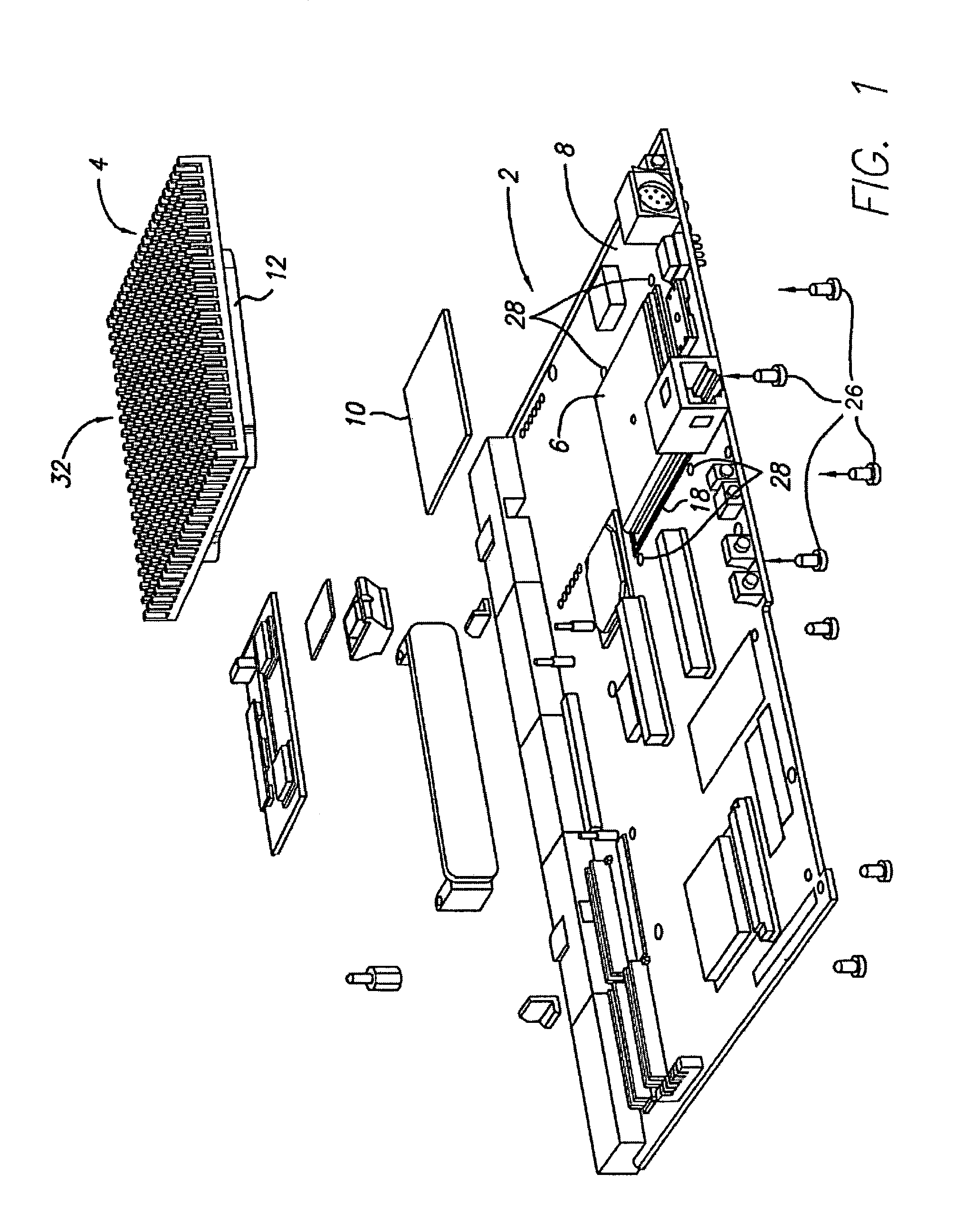
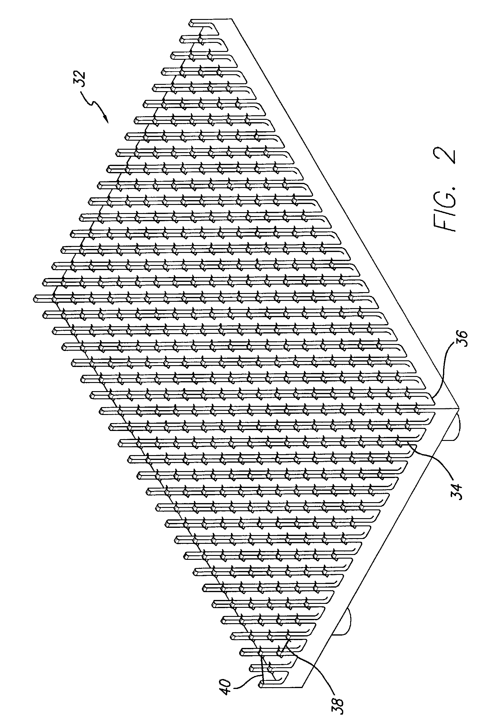
[0020]The present invention pertains to an electrical assembly 2 that includes a heat dissipation device 4, an electrical device 6 capable of emitting thermal energy and electromagnetic interference, and a circuit board 8. A first embodiment of the electrical assembly 2, shown in FIG. 1, incorporates a first embodiment of a heat dissipation device 4 of the invention. The first embodiment of the heat dissipation device incorporates both heat dissipation features, such as a plurality of fins 34 disposed in a matrix orientation 32, and EMI reduction features, such as an EMI fence 12 grounded to the circuit.

[0021]The circuit board 8 is generally one that is used in a computing device or system (not shown), such as a personal computer or a work station. Specific examples of systems in which electrical assemblies 2 and heat dissipation devices 4 of the invention are used include the CT 410, CT 810, CT 400, and CT 800 systems, all manufactured by Sun Microsystems. The heat dissipation devi...


PUM


Abstract

An electrical assembly comprising a circuit board an electrical device, and a heat dissipation device. The electrical device is capable of emitting thermal energy and electromagnetic interference (EMI). The electrical device is secured to the circuit board. The heat dissipation device is secured to the circuit board and is in thermal communication with the electrical device. The heat dissipation device also includes a continuous EMI fence and a plurality of fins disposed in a matrix orientation. The fins are spaced from one another to allow for efficient heat dissipation and have a substantially square cross-sectional shape.

Description

BACKGROUND OF THE INVENTION[0001]1. Field of the Invention[0002]The present invention relates to an electrical assembly having heat dissipation and electromagnetic interference reduction features.[0003]2. Description of Related Art[0004]Electrical devices, and central processing units in particular, draw high power and produce more heat than can be convected away from the dies of the device. If the die temperature exceeds acceptable levels, the device will either cease functioning, not operate at acceptable levels, and / or function in an unreliable manner. In addition, many electrical devices emit electromagnetic interference (EMI) that can adversely affect nearby electronics or electronic communication. The Federal Communication Commission of the U.S. government and industry agencies, such as Telcordia and United Laboratories, have established and verified EMI limits for such electrical devices.[0005]To address this problem, heat dissipation devices are used to convect heat away fro...

Claims


Application Information

Patent Timeline
Patent Type & Authority Patents(United States)
IPC IPC(8): H05K1/00H01L23/40H01L23/552H05K7/20H05K9/00
CPCH01L23/4006H01L23/552H05K9/002F28F3/022H01L2924/0002H01L2924/00
Inventor STEWART, THOMAS E.FURUTA, STEVEN J.
Owner ORACLE INT CORP
Why Eureka
Try Eureka