
Axisymmetric emittance-compensated electron gun

a technology of emittance compensation and electron gun, which is applied in the direction of discharge tube electron gun, electric discharge tube, accelerator, etc., can solve the problems that the energy consumed in generating these electrons may be considered as wasted energy, and achieve the effect of reducing or eliminating certain sources of emittance growth, facilitating the placement of emittance-compensating solenoids, and thorough optimization of emittance compensation

Inactive Publication Date: 2006-10-03
ADVANCED ENERGY SYST
View PDF6 Cites 4 Cited by
  • Summary
  • Abstract
  • Description
  • Claims
  • Application Information

AI Technical Summary

Benefits of technology

[0003]The present invention is directed to a system and method which substantially reduces or eliminates certain sources of emittance growth and allows more thorough optimization of emittance compenstation. In particular, certain embodiments of the electron gun of the present invention provides an architecture that permits easier placement of emittance-compensating solenoids and permits greater flexibility in cavity design.
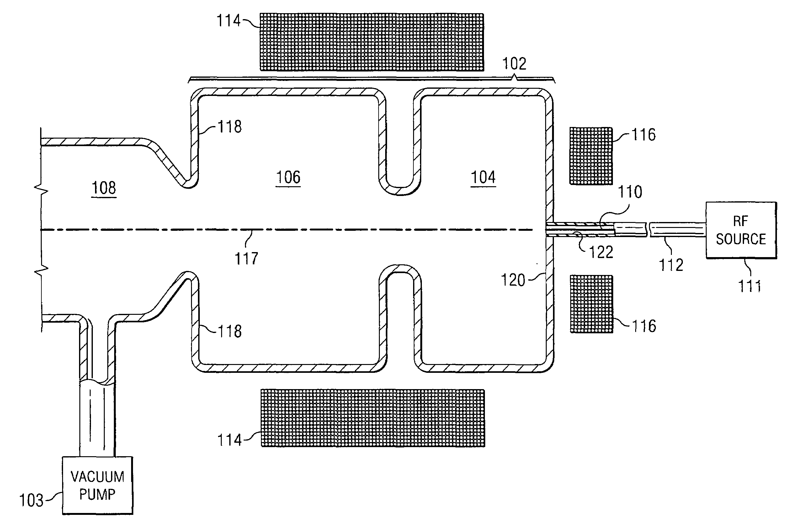
[0006]Important technical advantages of certain embodiments of the present invention include easier solenoid placement. The axisymmetric design of certain embodiments allows a cavity design without protrusions used to introduce RF energy. Thus, the solenoid's position may be adjusted without having to compensate for the presence of such protrusions.
[0007]Other important technical advantages of certain embodiments of the present invention include flexible cavity size. In certain embodiments, the cavity wall surrounding the electron filament may be adjusted to change the resonance of the cavity of the electron gun. These adjustments allow the electron gun to be tuned to a variety of frequencies depending on the intended use. Furthermore, because the position of the solenoid may also be adjusted in certain embodiments, the emittance compensation of the new configuration may be corrected for the new cavity size.

Problems solved by technology

Because these electrons do not travel within the beam of the electron gun, the energy consumed in generating these electrons may be considered as wasted energy.

Method used


Image

  • Axisymmetric emittance-compensated electron gun
  • Axisymmetric emittance-compensated electron gun

Examples


Embodiment Construction

[0011]FIG. 1 illustrates an electron gun 100 according to a particular embodiment of the present invention. Cavity 102 comprises one or more cells of conductive material enclosing volumes of space. In the particular embodiment depicted, cavity 102 is a one-and-a-half cell cavity that includes a half-cell 104 and one booster cell 106. However, it should be understood by one skilled in the art that the size and number of cells in the cavity may be selected to produce any desired resonance for a selected wavelength and power of RF input, and the depicted embodiment is only one example of cavity 102. Cavity 102 may be evacuated by vacuum pump 103 so that the electron beam is not scattered from air molecules within cavity 102.

[0012]Exit channel 108 provides a means for the electron beam to exit the electron gun 100. Exit channel 108 is typically circular with the radius of exit channel 108 aperture selected to minimize transverse non-linear fields.

[0013]Cathode 110, with longitudinal axi...


PUM


Abstract

An electron gun includes a cathode, a cavity, and an energy input. The cavity resonates at a particular frequency, and the cathode generates an electron beam along its longitudinal axis when driven by resonant electromagnetic radiation of the particular frequency. The energy input introduces electromagnetic radiation of the particular frequency into the cavity along the longitudinal axis of the cathode.

Description

TECHNICAL FIELD[0001]This invention relates in general to RF electron guns, and more particularly to an axisymmetric emittance compensated electron gun.BACKGROUND OF THE INVENTION[0002]Electron guns generate and accelerate narrowly focused beams of electrons. In a radio frequency (RF) electron gun, the electrons are accelerated with RF energy. The transverse emittance of the electron beam refers to the electrons that travel in a direction other than along the axis of the beam. Because these electrons do not travel within the beam of the electron gun, the energy consumed in generating these electrons may be considered as wasted energy. Consequently, it is desirable to have an electron gun structure that minimizes transverse emittance.BRIEF SUMMARY OF THE INVENTION[0003]The present invention is directed to a system and method which substantially reduces or eliminates certain sources of emittance growth and allows more thorough optimization of emittance compenstation. In particular, ce...

Claims


Application Information

Patent Timeline
IPC IPC(8): H05H7/00H05H9/00
CPCH01J3/02H05H7/18H05H15/00
Inventor BLUEM, HANS PETER
Owner ADVANCED ENERGY SYST
Learn More