Method and system for seafloor geological survey using vertical electric field measurement

a technology of electric field and seafloor, applied in the direction of reradiation, detection using electromagnetic waves, instruments, etc., can solve the problems of dramatic loss of electric and magnetic field power on the seafloor at periods shorter than 1000 seconds, and certain structures such as sediments buried under salt, basalt or carbonate have poor seismic performance and productivity,

Inactive Publication Date: 2006-10-03
RGT UNIV OF CALIFORNIA
View PDF16 Cites 44 Cited by
  • Summary
  • Abstract
  • Description
  • Claims
  • Application Information

AI Technical Summary

Problems solved by technology

For example, certain structures such as sediments buried under salt, basalt or carbonate have poor seismic performance and productivity.
These structures generate strong reflections and reverberations, making imaging of the buried sediments difficult using acoustic methods alone.
In the past, one primary reason for the limited use of MT for seafloor mapping was that high frequencies are rapidly attenuated by seawater, leading to a dramatic loss of electric and magnetic field power on the seafloor at periods shorter than 1000 seconds.
Previous attempts to measure vertical e-fields have used noisy, tethered instruments, e.g., electrodes attached at intervals along a length of flexible cable which is dragged behind a vessel.
These prior art systems also used low frequency amplifiers such that they were subject to the above-described frequency limitations for application to seafloor oil exploration.
However, these known methods have failed to recognize and / or take advantage of the vertical electric field and its ability to measure lateral variations in seafloor subsurface structure.

Method used


Image

  • Method and system for seafloor geological survey using vertical electric field measurement
  • Method and system for seafloor geological survey using vertical electric field measurement
  • Method and system for seafloor geological survey using vertical electric field measurement

Examples


case 114

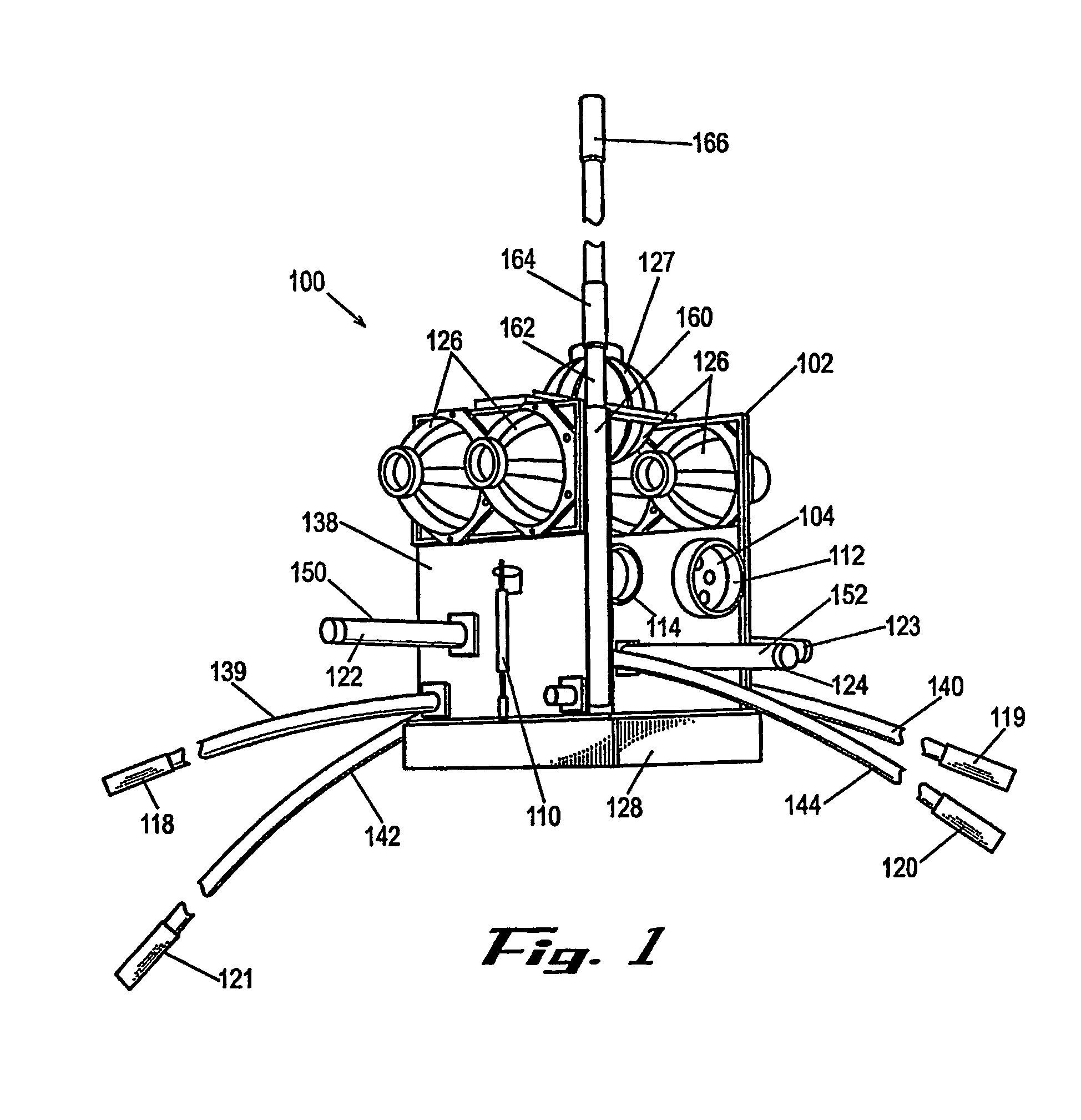
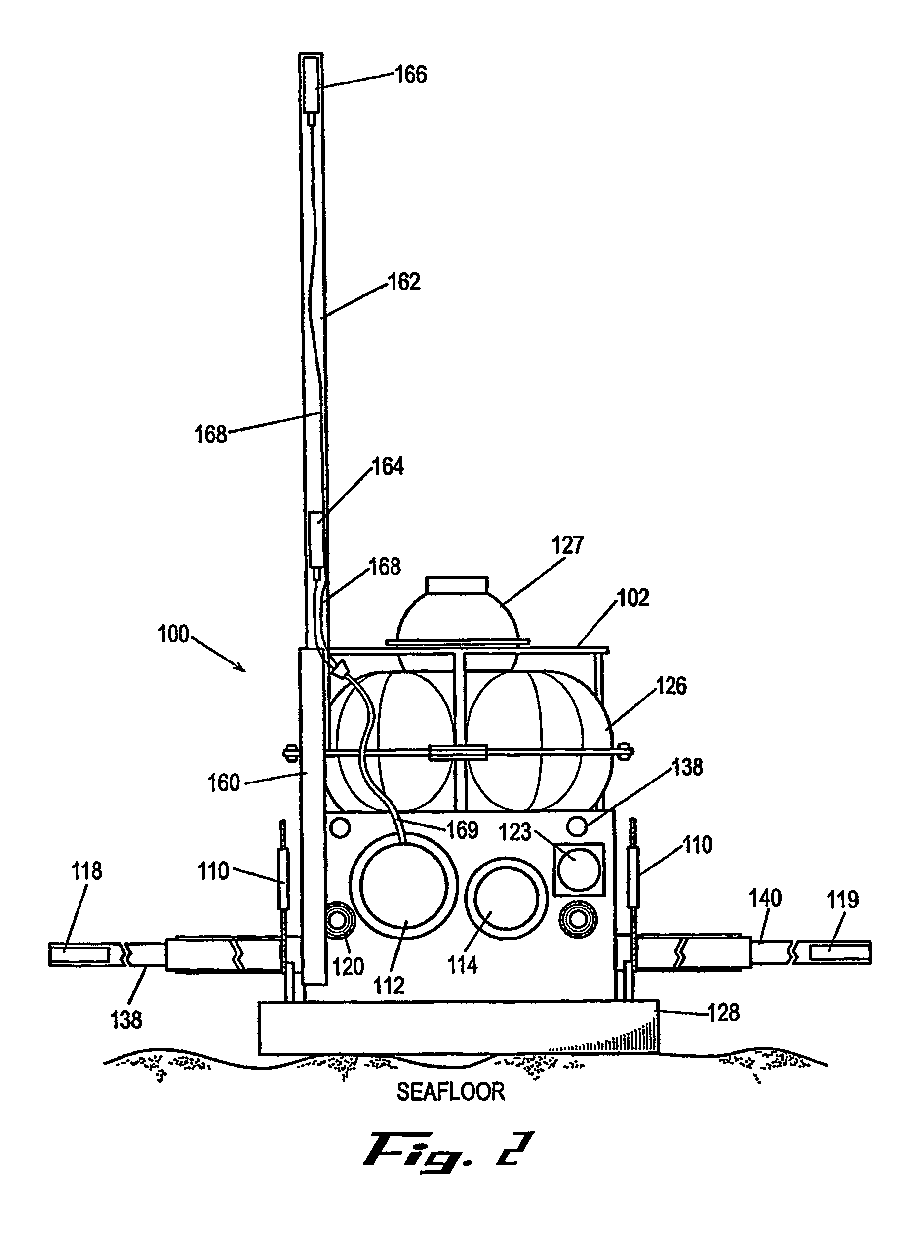
[0025]Pressure case 114 is constructed in a manner similar to that of case 112, with appropriate ports to allow connection to cables for electrical communication with other electrical components. Other types of pressure cases, including large capacity glass spheres, can also be used.

case 112

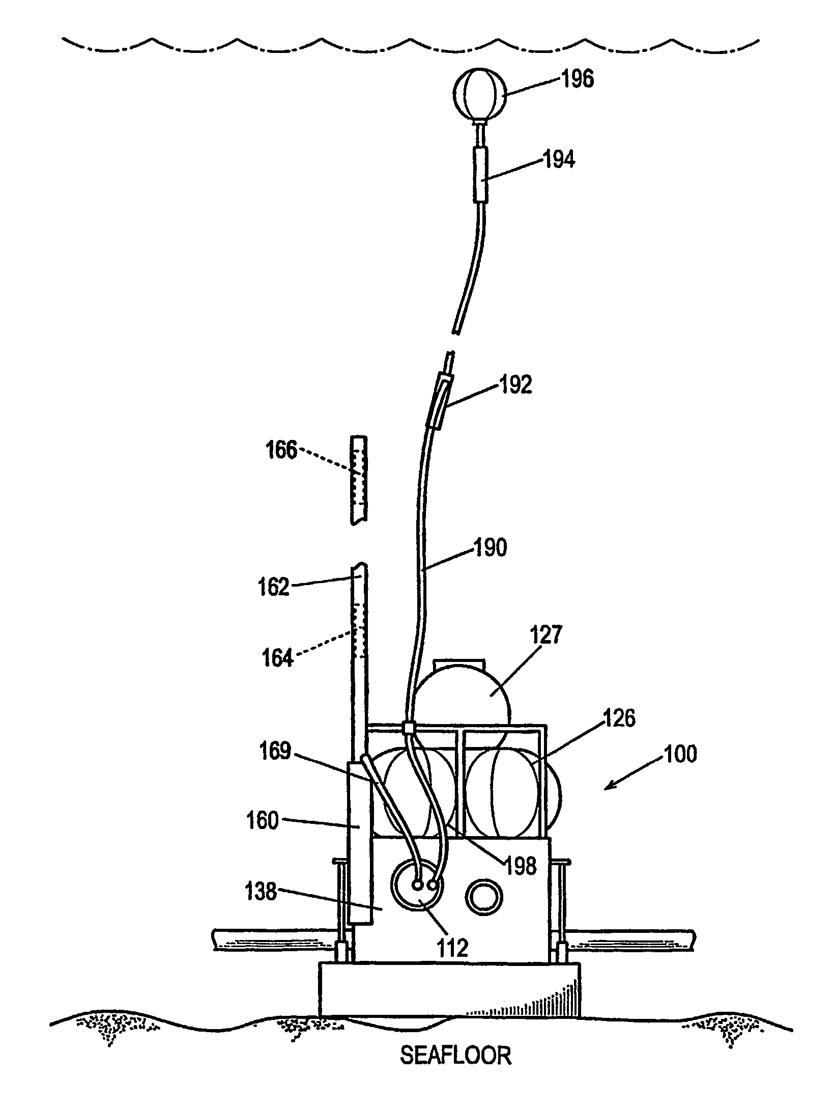
[0026]Pressure case 112 is supported in frame 138 to protect the instruments from damage during handling. Frame 138 also supports the floats 126, the pressure case 114 containing acoustic navigation / release system 116, the magnetometer coils 122–124, the electrode booms 139–142 and a concrete anchor which forms the bottom of the assembly.

[0027]Acoustic release system 116 provides means for releasing the unit 100 from the seafloor at the end of the recording period. In one embodiment, mechanical releases 110, 111 can be used to detach the anchor 128 from the rest of the unit, allowing the floats to lift the released components to the surface for recovery. A number of underwater acoustic release systems, such as those based on burn wire and other techniques, are commercially available and may be used for this purpose, including those manufacture by Benthos, Inc.

[0028]The horizontal electric field, or telluric, sensors are grounded dipole antennas. In the exemplary embodiment, booms 13...


PUM


Abstract

A system for mapping electrical conductivity of the seafloor incorporates a plurality of data logging units, where each unit (100) is an assembly adapted for deployment at a location on the seafloor for measurement of horizontal electric and magnetic fields. Rigidly attached and extending vertically from the unit assembly is a vertically-oriented substantially rigid arm (158) having a pair of vertically-displaced electrodes (160, 162) disposed on the arm to create a vertically-oriented dipole antenna. The electrodes are in electrical communication with an amplifier located within the assembly which generates an amplified signal which is then provided to a data logging processor also located within the assembly. The processor collects time series of amplified electric field and magnetic signals over a predetermined period of time.

Description

RELATED APPLICATIONS[0001]This application claims the priority of U.S. provisional application Ser. No. 60 / 387,784, filed Jun. 11, 2002. This application is related to U.S. application Ser. No. 08 / 670,939, now issued as U.S. Pat. No. 5,770,945. The disclosures of both applications are incorporated herein by reference in their entirety.FIELD OF INVENTION[0002]The present invention relates to measuring the electrical conductivity of the seafloor in a magnetotelluric or controlled source electromagnetic survey.BACKGROUND OF THE INVENTION[0003]The magnetotelluric (MT) method is an established technique which uses measurements of naturally occurring electromagnetic fields to determine the electrical resistivity, or conductivity, of subsurface rocks. An MT survey employs time series measurements of orthogonal components of the electric and magnetic fields, which define a surface impedance. This impedance, observed over a broad band of frequencies and over the surface, determines the elect...

Claims


Application Information

Patent Timeline
Patent Type & Authority Patents(United States)
IPC IPC(8): G01V3/00G01R33/02G01V1/00G01V3/08G01V3/12G01V3/15
CPCG01V3/082G01V3/083G01V3/12G01V3/15
Inventor CONSTABLE, STEVEN C.
Owner RGT UNIV OF CALIFORNIA
Why Eureka
Try Eureka