Polarization beam splitter and optical system using the same, and image displaying apparatus, using the same

a splitter and optical system technology, applied in the direction of instruments, polarising elements, projectors, etc., can solve the problems of limited use of an optical system, inability to improve, and difficulty in ensuring an angle characteristic widely, and achieves simple structure and design. , the effect of high extinction ratio

Inactive Publication Date: 2006-10-03
CANON KK
View PDF7 Cites 58 Cited by
  • Summary
  • Abstract
  • Description
  • Claims
  • Application Information

AI Technical Summary

Benefits of technology

[0023]Also, it is desirable that the polarization beam splitter have a shape of a square pole type having a diamond-shaped bottom surface obtained by two transparent members of substantially the same triangle pole shape having an isosceles triangle as a bottom surface having had their sides including the bottom sides of their respective isosceles triangles joined to each other. It is better if the first direction is disposed so as to be parallel to the diamond-shaped bottom surface.
[0029]Also, it is better if design is made such that a ray is incident on the polarized beam splitting layer within an angle range including the Brewster's angle determined by the refractive index of the medium of the optical members and the effective refractive index of the polarized beam splitting layer for light having a polarized component parallel to the first direction.
[0030]Also, it is better if the refractive index of the medium of the optical members and the effective refractive index of the polarized beam splitting layer for the light having the polarized component parallel to the first direction are made substantially equal to each other.
[0038]According to the present invention as previously described, regarding the polarization beam splitter, there is the effect that there can be realized a polarization beam splitter which is simple in both of structure and design, and yet has a high extinction ratio within wide ranges of wavelength characteristic and incidence angle characteristic.

Problems solved by technology

In the polarization beam splitter using the dielectric material multi-layer film, however, the condition of Brewster's angle is used for the transmission of P polarized light and therefore, the refractive indices of a prism glass material and the medium of the thin film are subject to the limitation of expression (2) above and also, it is difficult to secure an angle characteristic widely.
This is not improved even if the number of layers is increased.
In a polarization beam splitter with a high molecular material having birefringence sandwiched between prisms, the refractive index difference of the high molecular material between a normal ray and an abnormal ray is not great and therefore, to effect total reflection, the incidence angle must be about 60° or greater, and this leads to the problem that the use of a usable optical system is limited.
Also, this element uses a high molecular material or the like as a birefringent element and is therefore inferior from the viewpoints of heat resistance and light resistance.
In the polarization beam splitter of the laminated rectangular grating type using SWS, the construction is complicated and the manufacturing cost is high, and the condition of the Brewster's angle is used for the transmission of P polarized light and therefore, like the dielectric material multi-layer film, it is difficult to obtain a wide angle characteristic.
Particularly, as is apparent from the structure of the grating shown in FIG. 11, as the incidence angle becomes great, the refractive index difference between TE and TM becomes null and therefore, the increase in the reflectance at an incidence angle exceeding the Brewster's angle is greater than when dielectric material thin film is used, and this hinders widening the angle characteristic and therefore, an element having sufficient performance cannot be obtained.

Method used


Image

  • Polarization beam splitter and optical system using the same, and image displaying apparatus, using the same
  • Polarization beam splitter and optical system using the same, and image displaying apparatus, using the same
  • Polarization beam splitter and optical system using the same, and image displaying apparatus, using the same

Examples


first embodiment

[FIRST EMBODIMENT]

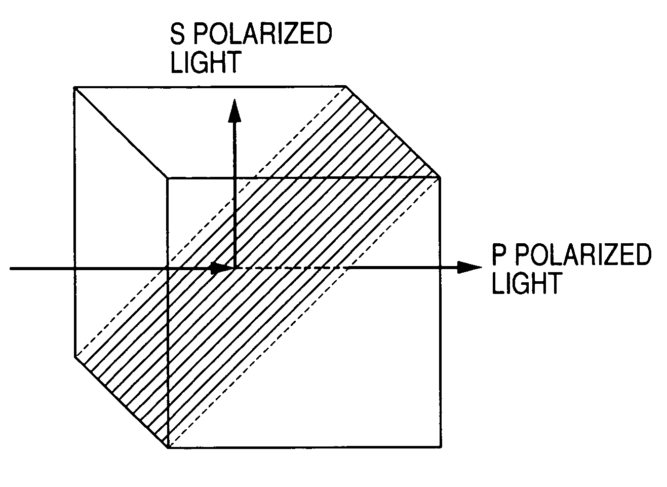
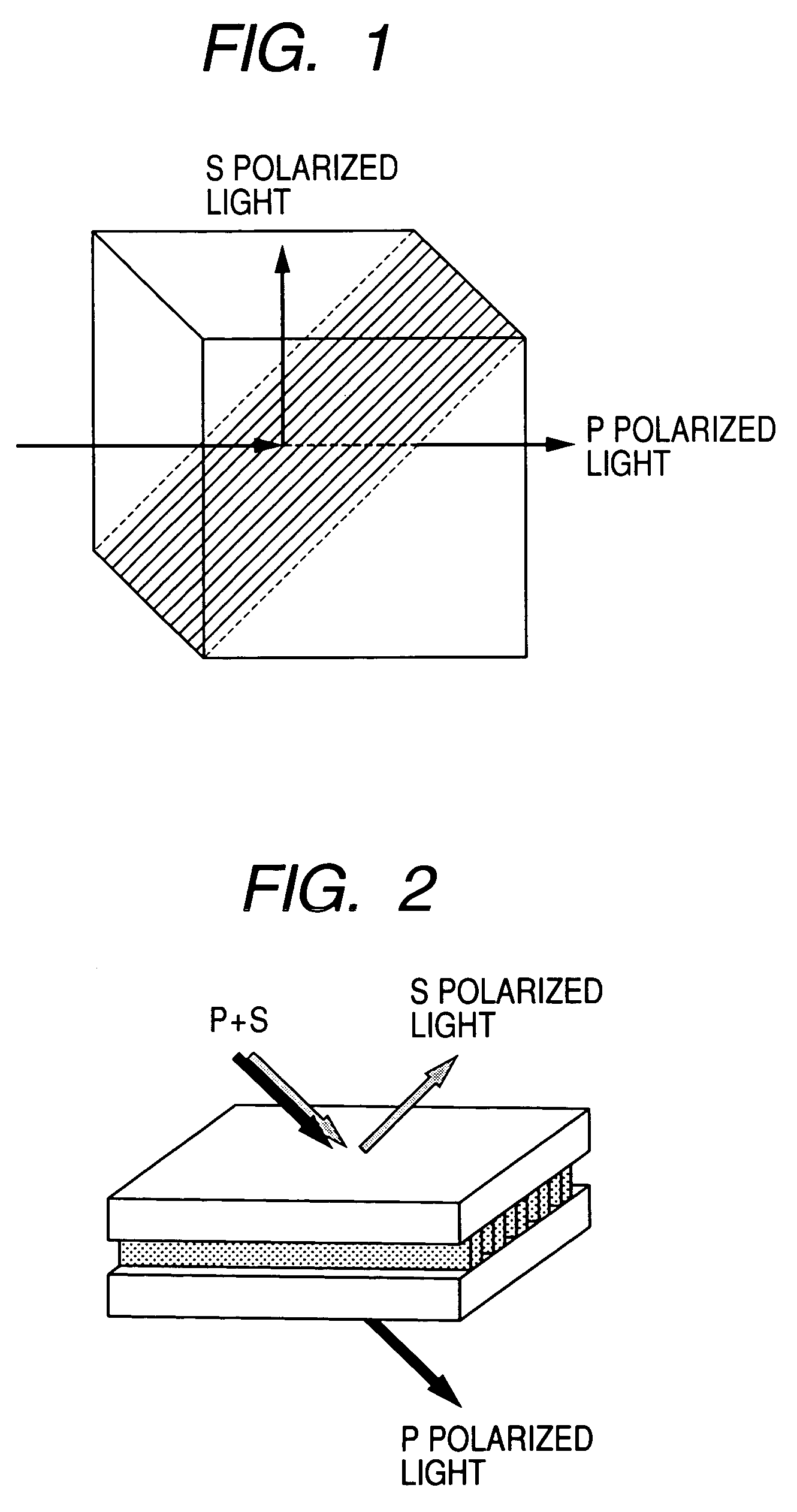
[0052]FIG. 1 shows the construction of a polarization beam splitter according to a first embodiment of the present invention. Tables 1 and 2 below show the numerical values of the constructions by Design Examples 1 and 2 of a grating of SWS used in this first embodiment.

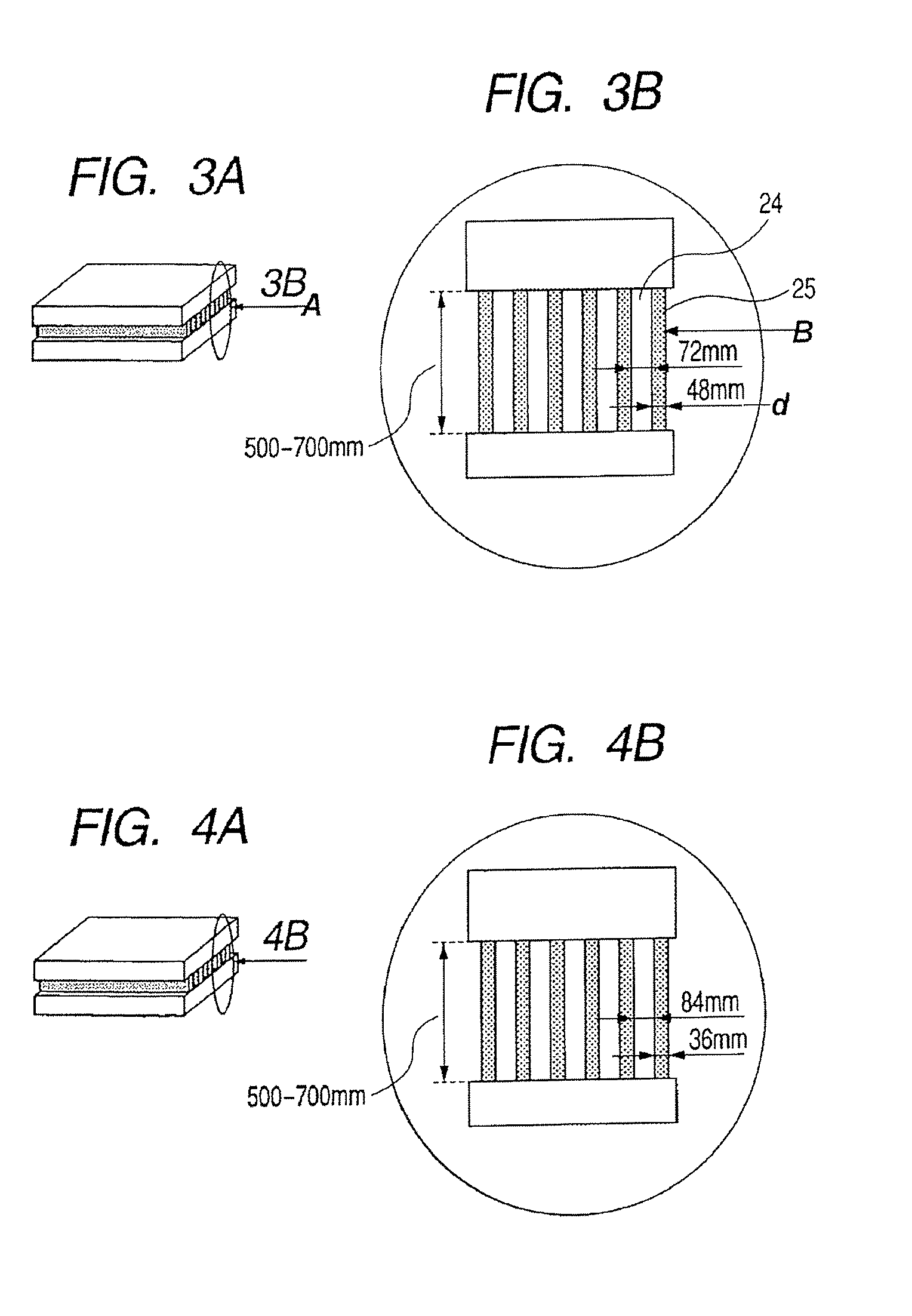
[0053]Referring to FIG. 1, a polarized beam splitting layer is inclined at 45° with respect to the incidence surface of a prism. The grating of SWS, as shown in FIG. 2, is disposed in parallel to the incidence plane, and is designed to reflect S polarized light and transmit P polarized light therethrough. This grating of SWS adopts such a construction as shown in FIGS. 3A and 3B, and as shown in FIG. 3B, the cross-sectional structure of the grating (a direction parallel to this grating, i.e., a direction perpendicular to the plane of the drawings sheet of FIG. 3B, is referred to as A direction) is of rectangular grating structure (the pitch direction of this grating, i.e., a direction parallel to th...

second embodiment

[SECOND EMBODIMENT]

[0067]FIGS. 4A and 4B show the grating structure of SWS of a polarization beam splitter according to a second embodiment of the present invention. In Tables 1 and 2 below, there is shown the construction by Design Example 2 of the grating of SWS according to the second embodiment. As in the first embodiment, a polarized beam splitting layer is inclined at 45° with respect to the incidence surface of the prism, and is designed to reflect S polarized light and transmit P polarized light therethrough. The cross-sectional structure of the grating is rectangular grating structure in which air and TiO2 are alternately repeated. As shown in Table 2, it is structure satisfying conditional expressions (7) and (8). In the second embodiment, f is set so as to become a value approximate to the lower limit of the condition of expression (7), whereby regarding the total reflection of expression (8), the angle characteristic can be set widely on the short wavelength side.

[0068]F...

third embodiment

[THIRD EMBODIMENT]

[0069]FIG. 5 shows the construction of a polarization beam splitter prism according to a third embodiment of the present invention. The polarization beam splitter of Design Example shown in Table 1 and Table 2 is inserted in the prism inclined into a diamond shape. Incident light from the left side of FIG. 5 is incident on a prism surface perpendicularly thereto, and is incident on the polarization beam splitter at an angle greater than 45°. Regarding the light being totally reflected, a greater incidence angle is more advantageous, but the prism is inclined into a diamond shape at about 10° as described above, whereby the incidence angle can be changed by 5°.


PUM


Abstract

In a conventional polarization beam splitter, it has been difficult to improve the angle-dependence characteristic of polarized beam splitting efficiency even if the number of layers is increased. The polarization beam splitter of the present invention is a polarization beam splitter having a polarized beam splitting layer having structure in which a plurality of gratings parallel to a first direction are periodically disposed in a second direction orthogonal to the first direction, and of light incident on the polarization beam splitter, chiefly light of a polarized component parallel to the first direction is transmitted therethrough, and chiefly light of a polarized component parallel to the second direction is reflected.

Description

BACKGROUND OF THE INVENTION[0001]1. Field of the Invention[0002]This invention relates to a polarization beam splitter used in lights of a plurality of wavelengths or bands, and relates, for example, to various optical apparatuses such as an image taking optical system, a projection optical system (projector), an image processing apparatus and a semiconductor manufacturing apparatus.[0003]2. Description of Related Art[0004]There is known a polarization beam splitter using dielectric material multi-layer film comprising two kinds of media. As shown in FIG. 12 of the accompanying drawings, it uses transmission (19) at Brewster's angle regarding P polarized light (18) incident on multi-layer film 17, and effects reflection (21) by the interference of the multi-layer film regarding S polarized light (20).[0005]Generally, when the refractive index of the medium on the incidence side with an interface as the boundary is defined as n1 and the refractive index of the medium on the emergence...

Claims


Application Information

Patent Timeline
Patent Type & Authority Patents(United States)
IPC IPC(8): G02B5/30G02B27/28G03B21/00
CPCG02B5/3025G02B27/283
Inventor MOMOKI, KAZUHIKOOHTAKA, KEIJI
Owner CANON KK
Why Eureka
Try Eureka