
X-ray tube with rotary anode

a technology of x-ray tubes and hollow anodes, applied in the field of x-ray tubes, can solve the problems of disadvantage, high cost of manufacturing, and complicated design of x-ray tubes, and achieve the effect of improving performance and simple and cost-effective technology

Inactive Publication Date: 2006-10-03
SIEMENS AG
View PDF13 Cites 2 Cited by
  • Summary
  • Abstract
  • Description
  • Claims
  • Application Information

AI Technical Summary

Benefits of technology

"The present invention provides an improved x-ray tube that is simple and cost-effective. The tube has a rotating anode with a fluid to dissipate heat. The anode plate is in direct contact with the fluid, which allows for effective heat dissipation. The tube can be operated with a higher capacity for a smaller structure. The invention uses a liquid metal that has high heat conductivity, which further enhances heat transfer. The anode shaft extends into a recess or a bore in the anode plate, which increases the contact surface and improves heat dissipation. The intervening space is appropriately bordered by a seal to prevent overheating. The anode shaft can be hollow and have a cooling device to prevent overheating. The thickness of the anode plate increases towards the anode shaft to provide a larger contact surface."

Problems solved by technology

The high performance drive needed for the rotary piston is, however, disadvantageous.
This x-ray tube is complicated in terms of design and therefore expensive to manufacture.
X-ray tubes with hollow anode plates generally require a high manufacturing expenditure,

Method used


Image

  • X-ray tube with rotary anode
  • X-ray tube with rotary anode
  • X-ray tube with rotary anode

Examples


first embodiment

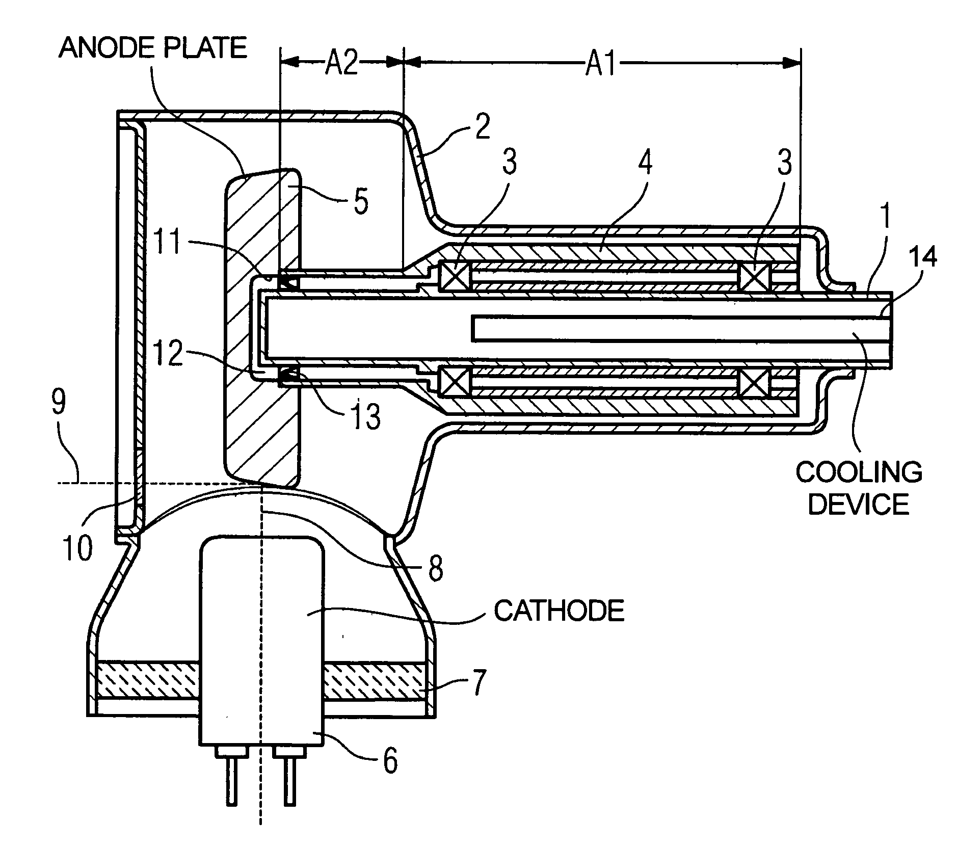
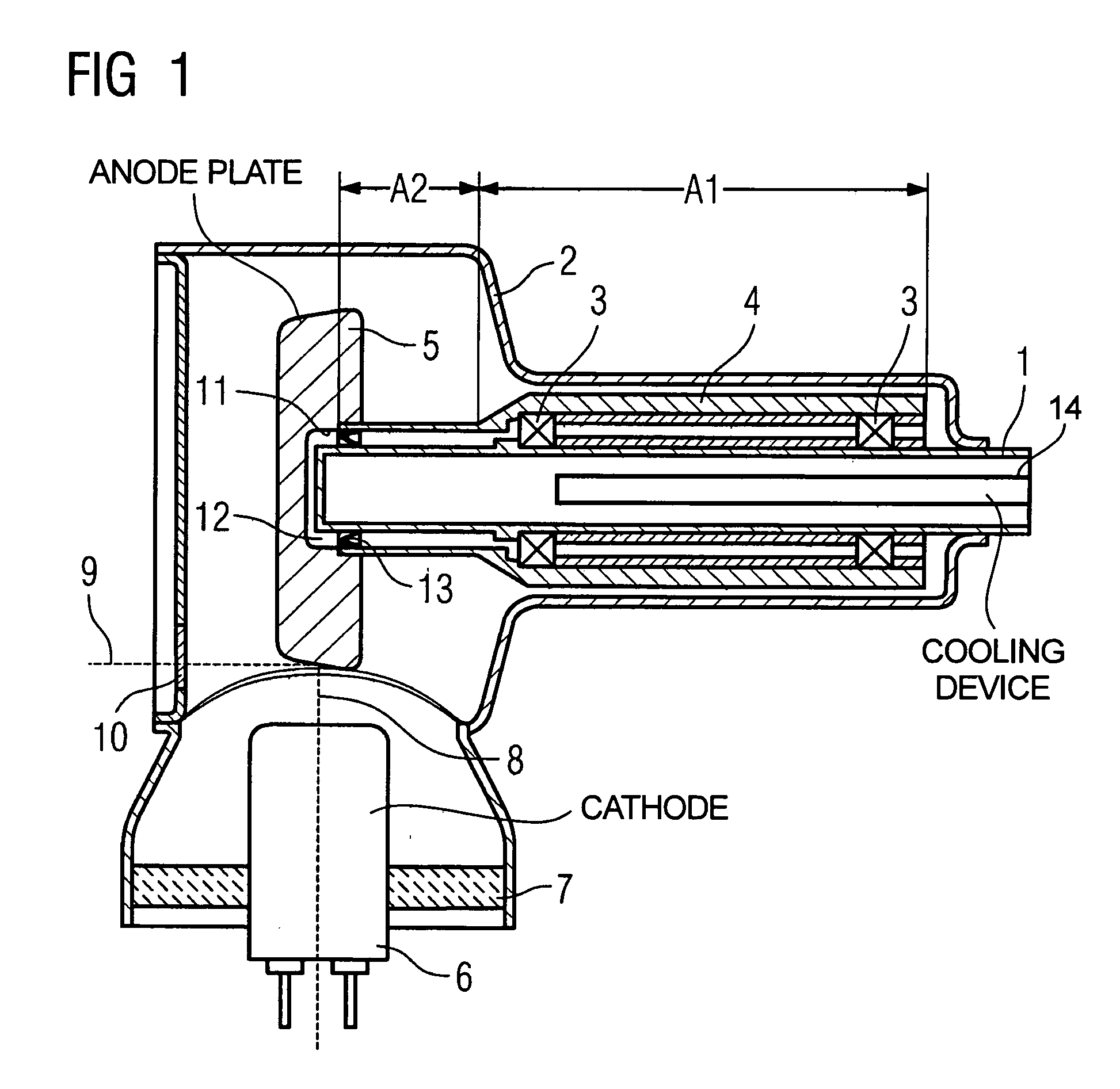
[0022]In the x-ray tube shown In FIG. 1, the anode plate 5 has a recess 11 into which the anode shaft 1 protrudes. An intervening space 12 formed between a closed end of the anode shaft 1 and the recess 11 is sealed by means of axial face seals 13 which are provided between the anode shaft 1 and the second section A2 of the anode tube 4. A metal (not shown here) with a melting point of less than 100° C. is accommodated in the intervening space 12, for example, GaInSn.

second embodiment

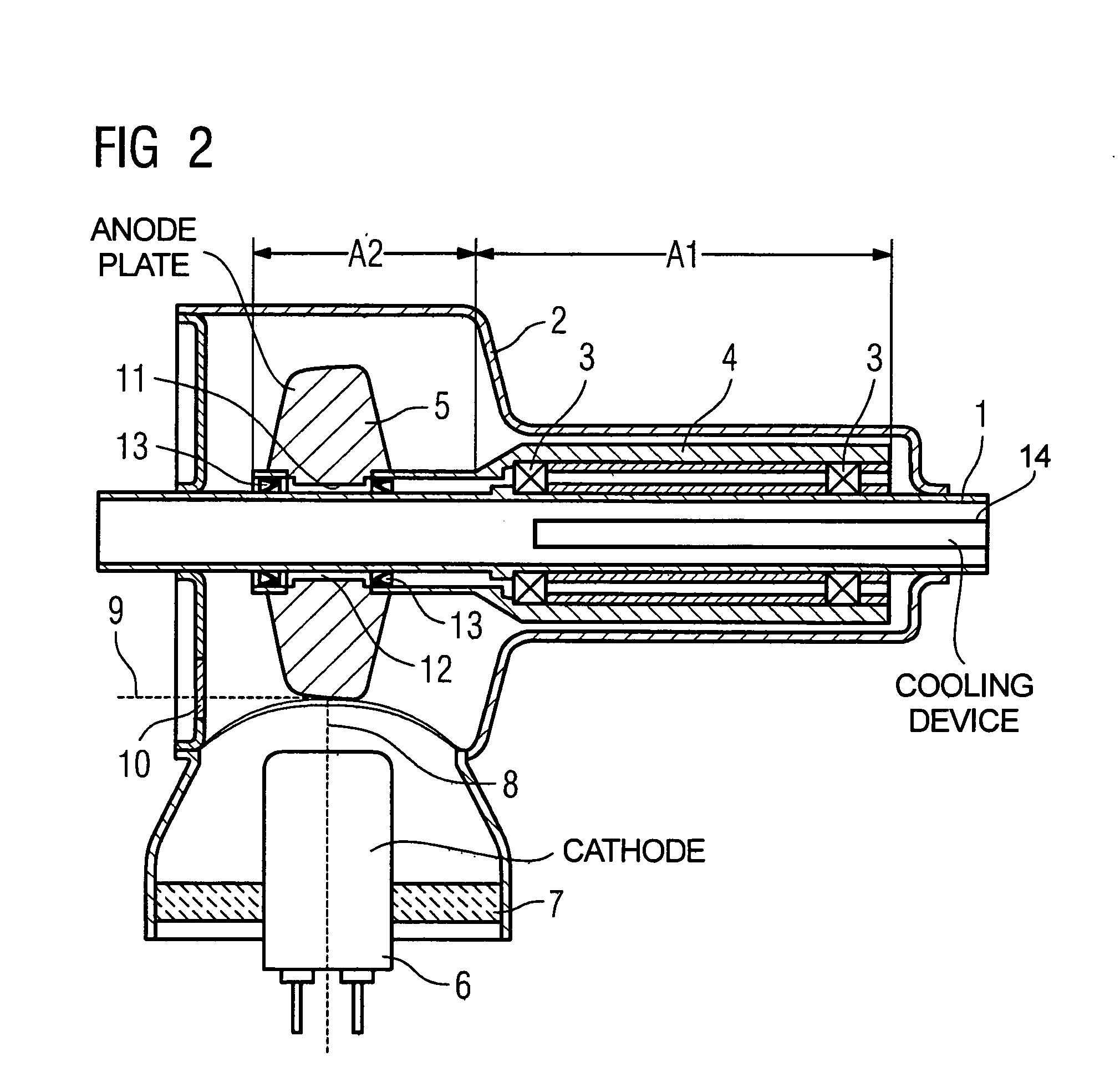
[0023]In the x-ray tube shown in FIG. 2, the anode plate 5 has a central bore through which the anode shaft 1 as well as the second section A2 of the anode tube 4 extend. To seal the intervening space 12, two axial face seals 13 are provided between the second section A2 of the anode tube 4 and the anode shaft 1, of which one is arranged in the region of a top side of the anode plate 5 and the other is arranged in the region of a bottom side of the anode plate 5. The anode plate 5 here exhibits a thickness increasing from its circumferential edge toward the shaft 1. The cross-section can—as shown in FIG. 2—be trapezoidal.

[0024]Operation of the inventive x-ray tube is as follows:

[0025]As a result of the electron beam 8 acting on the anode plate 5, it is heated. Due to the rotation of the anode plate 5, it heats uniformly. Due to the contact of the liquid metal contained in the intervening space 12, the heat of the anode plate 5 is effectively dissipated to the rigid anode shaft 1, wh...


PUM

PropertyMeasurementUnit
temperatureaaaaaaaaaa
melting pointaaaaaaaaaa
capillary structureaaaaaaaaaa

Abstract

An x-ray tube has an anode plate connected to an anode tube that is mounted such that it can rotate around a rigid anode shaft. To improve the heat dissipation from the anode plate, a liquid for dissipation of heat to the anode shaft is accommodated in an intervening space formed between the anode shaft and the anode plate.

Description

BACKGROUND OF THE INVENTION[0001]1. Field of the Invention[0002]The present invention concerns an x-ray tube of the type having a rotary anode that rotates on a rigid shaft.[0003]2. Description of the Prior Art[0004]An x-ray tube of the above type is known from Japanese Application 3228992. In this known x-ray tube, an node plate Is attached to the closed end of an anode tube via a short, rigid axle. The anode tube is mounted on the rigid axle such that it can rotate. In the area of the end of anode tube, a fluid metal is incorporated for improving heat dissipation from the anode plate. Although, the heat transfer from such an anode plate to a cooling device incorporated into the anode axle is improved, in the manner a further improvement of the cooling of the anode plate would be desirable to improve the overall performance of such an x-ray tube.[0005]Rotary piston radiators are known from German OS 197 41 750, German PS 198 51 853 as well as German OS 199 56 491 wherein a rotary d...

Claims


Application Information

Patent Timeline
Patent Type & Authority Patents(United States)
IPC IPC(8): H01J35/10H01J35/24H01J35/26H01J35/28
CPCH01J35/106H01J2235/1204H01J2235/1208H01J2235/1266H01J2235/1279
Inventor APEL, MANFREDBAULE, HOLGERFREUDENBERGER, JORG
Owner SIEMENS AG
Learn More