Battery mounting arrangement for electrically powered vehicle

a technology for mounting arrangements and electric vehicles, which is applied in the direction of propulsion/propulsion by batteries/cells, cycle equipment, cell components, etc., can solve the problems of prior arrangements that have not protected the battery from foreign material contamination, inability to adequately maintain the desired open space, and difficulty in removing the battery

Inactive Publication Date: 2006-10-10
YAMAHA MOTOR CO LTD
View PDF24 Cites 59 Cited by
  • Summary
  • Abstract
  • Description
  • Claims
  • Application Information

AI Technical Summary

Benefits of technology

[0008]Accordingly, a need exists for a battery mounting arrangement for an electrically driven scooter which overcomes the limitations of the prior art. Preferably, such a battery mounting arrangement permits the scooter to retain a traditional appearance.

Problems solved by technology

One challenge presented in adapting an electric power unit in a scooter is the positioning of a suitably sized battery, while still maintaining the traditional appearance of a scooter.
For example, prior electrically driven scooters have been unable to adequately maintain the desired open space between the handle bar assembly and the seat assembly.
In addition, prior battery positions have rendered removal of the battery difficult.
Furthermore, prior arrangements have not protected the battery from contamination from foreign material, such as water, for example, to a satisfactory level.

Method used


Image

  • Battery mounting arrangement for electrically powered vehicle
  • Battery mounting arrangement for electrically powered vehicle
  • Battery mounting arrangement for electrically powered vehicle

Examples


Embodiment Construction

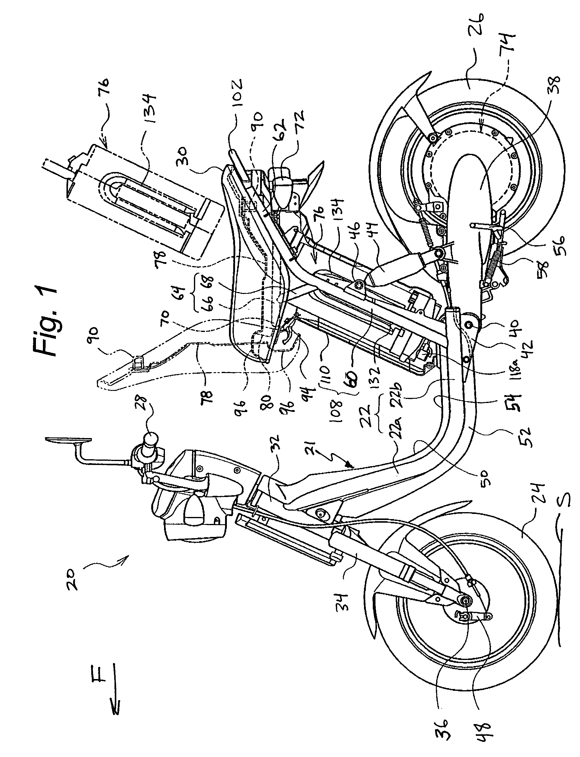
[0029]FIG. 1 illustrates an electrically powered scooter, referred to generally by the reference numeral 20. The scooter 20 incorporates a preferred embodiment of a battery and battery mounting arrangement of the present invention. The scooter 20 is described in general detail in order to assist the reader's understanding of a preferred environment of use of the present battery and battery mounting arrangement. However, it will be appreciated by one of ordinary skill in the art that the present battery and battery mount arrangement may also be incorporated for use with other types of vehicles, such as golf carts or other vehicles having more than two wheels, for example. The scooter 20 is described with reference to a coordinate system wherein a longitudinal axis passes lengthwise through the vehicle 20. A vertical, central plane generally bisects the scooter 20 and includes the central axis. A lateral plane is normal to the central, vertical plane. Right and left directions are des...


PUM

PropertyMeasurementUnit
angleaaaaaaaaaa
vertical dimensionaaaaaaaaaa
oblique angleaaaaaaaaaa

Abstract

An electrically-powered scooter including a front wheel, a rear wheel and a frame assembly. A handlebar assembly and a seat assembly are supported by the frame assembly. The frame assembly includes a left frame rail and a right frame rail spaced laterally from one another and extending between the handle bar assembly and the seat assembly. A battery support extends between the left and the right frame rails at a position intermediate the handle bar assembly and the seat assembly. A battery is supported by the battery support. In one arrangement, the battery support includes an enclosure defining a battery storage chamber. The enclosure includes a guide member configured to engage a guide recess of the battery to guide the battery into the battery storage chamber. In another arrangement, the battery may include a recharging port, an axis of which defines an oblique angle with an axis of the battery.

Description

RELATED APPLICATION[0001]This application is related to, and claims priority from, Japanese Patent Application No. 2002-237512, the entire contents of which is hereby expressly incorporated by reference herein.BACKGROUND OF THE INVENTION[0002]1. Field of the Invention[0003]The present invention relates, in general, to electrically powered scooters. More particularly, the present invention relates to a battery mounting arrangement for an electrically powered scooter.[0004]2. Description of the Related Art[0005]Due to concern for environmental damage associated with emissions from internal combustion engines, alternative means of propelling vehicles has received increased attention. Electric motors have been used to propel vehicles with some degree of success. However, batteries used to provide electricity to power the electric motors have been relatively large in size in order to provide an acceptable range of travel on a single charge of the battery. While battery size presents an i...

Claims


Application Information

Patent Timeline
Patent Type & Authority Patents(United States)
IPC IPC(8): B60R16/04B62J9/00B60K1/04B62J1/12B62M25/08H01M2/10
CPCB60K1/04B60L11/1822B60L11/1877B62K11/10B60L2200/12B62K2202/00B60Y2200/12B62K2208/00Y02T10/7005Y02T10/705Y02T10/7072Y02T90/124Y02T90/14B62K2204/00B60L50/66B60L53/80B62J43/16B62J43/28Y02T10/70B62M25/08Y02T90/12
Inventor KOHDA, HIDEOKOIZUMI, ATSUSHIOKAMOTO, IKUONAGASE, TAKESHITERADA, JUNJI
Owner YAMAHA MOTOR CO LTD
Why Eureka
Try Eureka