Image reading apparatus

Inactive Publication Date: 2006-10-10
NIPPON SHEET GLASS CO LTD
View PDF11 Cites 25 Cited by
  • Summary
  • Abstract
  • Description
  • Claims
  • Application Information

AI Technical Summary

Benefits of technology

[0020]It is one object of the present invention to provide an image reading apparatus of a contact image sensor type in which a resolution ca

Problems solved by technology

Therefore, inconveniently, the lens is not focused to the original surface and the resolution deteriorates.
However, since the area light source comprising the light guide plate and the R-, G-, and B-LED light sources has an illuminance which is reduced as it exists more apart from the R-, G-, and B-LED light sources, it is not possible to manufacture the area light source having a uniform illuminance over a wide area.
Consequently, the area light source comprising the light guide plate and the R-, G-, and B-LED light sources cannot read the light transmitting original having a wide area.
However, when the light transmitting original such as a polyester-system film is placed onto the glass surface of the original base similarly to the sheet original, it is adhered to the glass surface, resulting in a problem in that a Ne

Method used


Image

  • Image reading apparatus
  • Image reading apparatus
  • Image reading apparatus

Examples


first embodiment

[0090]Hereinbelow, the present invention will be described with reference to the drawings.

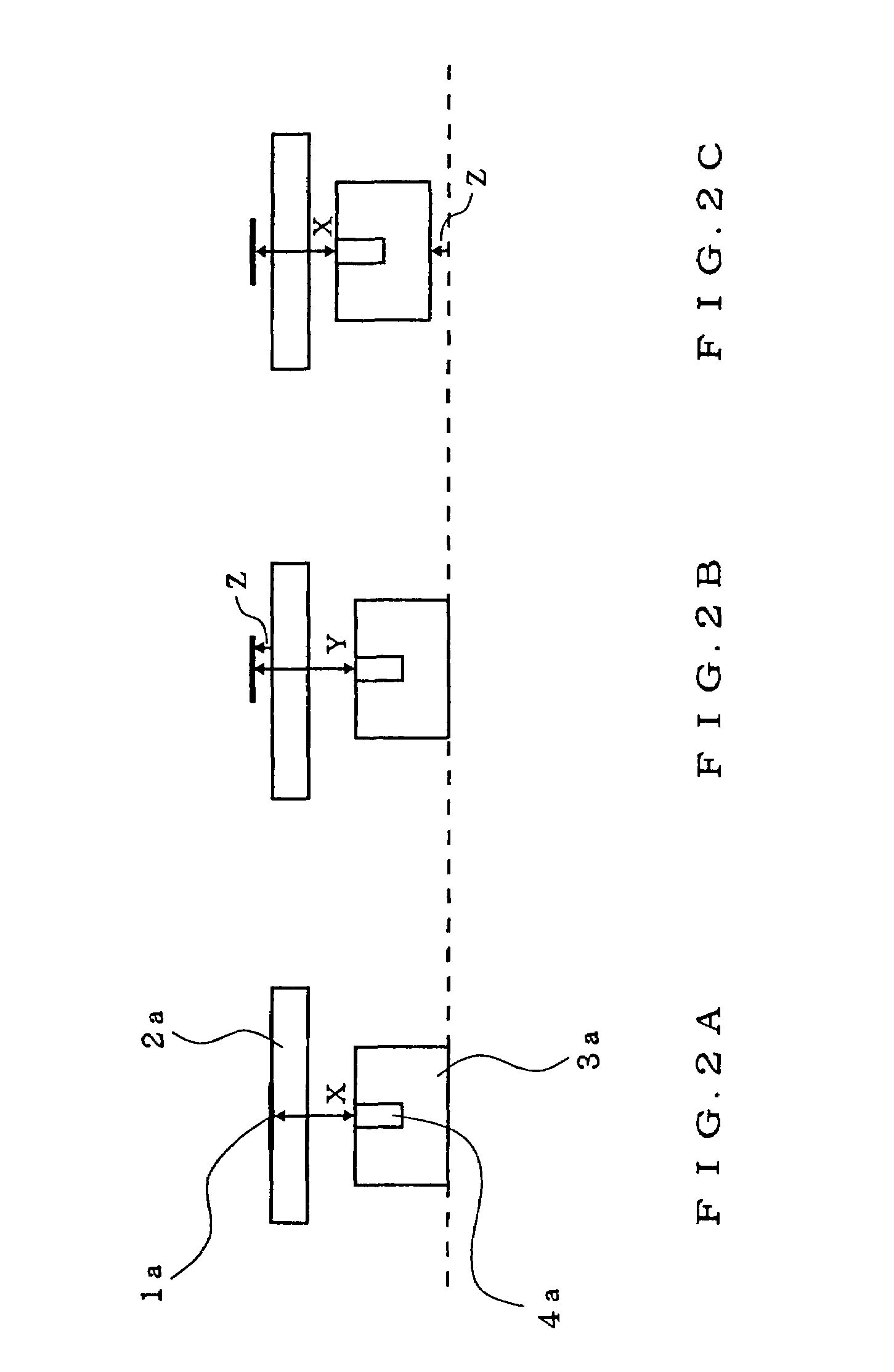
[0091]FIGS. 2A to 2C are schematic diagrams showing relationships between a light transmitting original and a contact image sensor (CIS) unit in a CIS-type image reading apparatus in the present invention.

[0092]Referring to FIG. 2A, an original surface of a light transmitting original 1a is adhered to a glass surface of an original base 2a and a lens is focused to the original surface. In this case, symbol X denotes a distance from the original surface to an incident side surface of a rod lens array 4a.

[0093]Referring to FIG. 2B, the original surface is apart from the glass surface of the original base 2a by a distance Z so that the light transmitting original 1a has a slide frame, and symbol Y denotes a distance from the original surface to the incident side surface of the rod lens array 4a. In this case, an equality of (Y=X+Z) is established.

[0094]As described above, in the CIS-type image re...

second embodiment

[0112]Next, the present invention will be described with reference to the drawings.

[0113]FIG. 9 is a cross-sectional view showing an image reading apparatus according to the second embodiment of the present invention. Referring to FIG. 9, the image reading apparatus comprises a main body 5c and an original cover 11a which can openably and closably be supported to the main body 5c. The main body 5c comprises a contact image sensor unit 3c which is longitudinal in a main scanning direction, and a guide rail 8d for guiding the contact image sensor unit 3c in a sub-scanning direction (perpendicular to the main scanning direction). The top of the main body 5c comprises an original base 2c made of a glass plate. The contact image sensor unit 3c provided in the proximity of the glass plate of the original base 2c, comprises therein a line sensor for receiving transmission light from a light transmitting original 1b and a magnet 12a at both ends in the longitudinal direction thereof.

[0114]T...

third embodiment

[0157]Next, the present invention will be described with reference to the drawings.

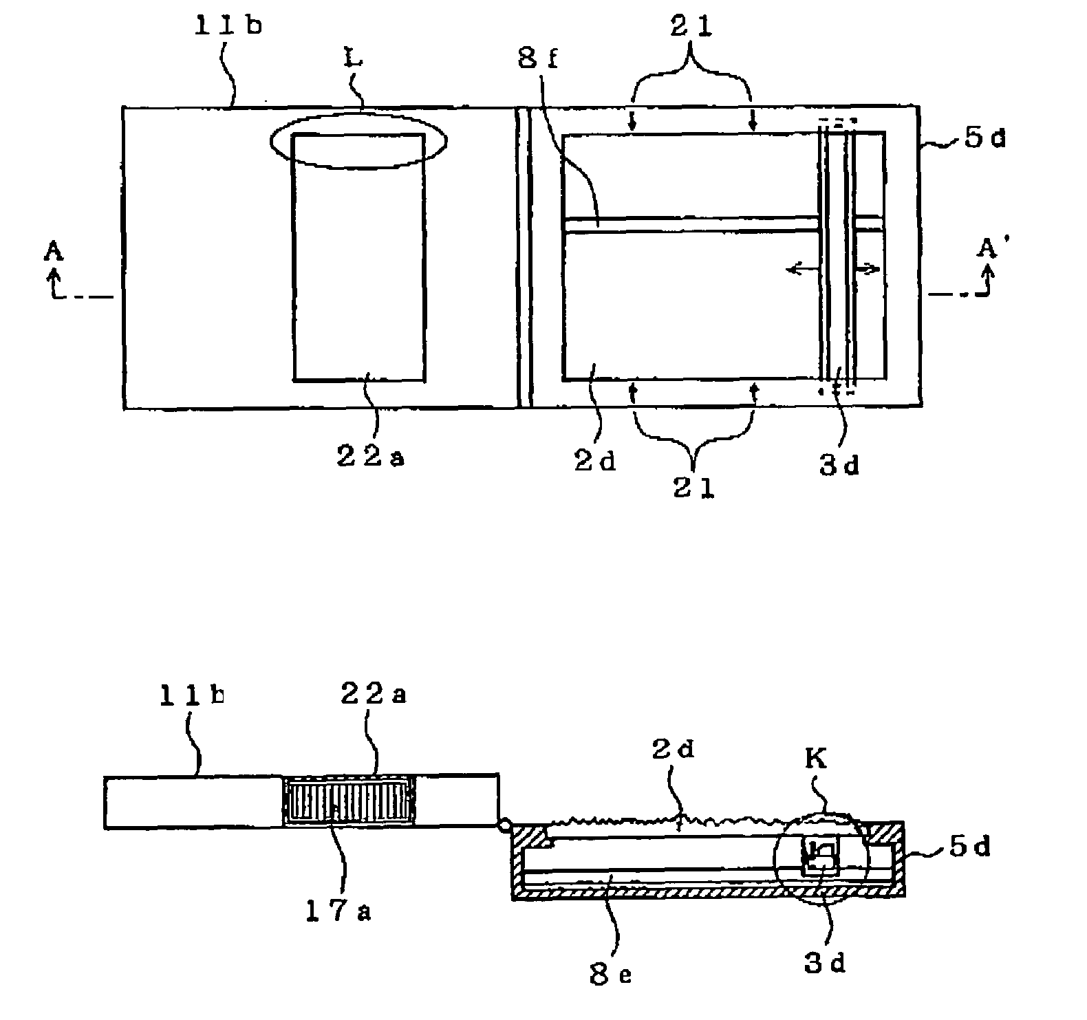
[0158]FIGS. 17A to 17F are diagrams showing an image reading apparatus of a contact image sensor unit type for reading the image of the light transmitting original and the sheet original, according to the third embodiment of the present invention.

[0159]FIG. 17A is a plan view of the image reading apparatus for reading images of the light transmitting original and the sheet original when an original cover is opened, FIG. 17B is a side view of the image reading apparatus when the original cover is opened, FIG. 17C is a cross-sectional view of the image reading apparatus along an A–A′ line of FIG. 17A, FIG. 17D is a plan view of the image reading apparatus when the original cover is closed, FIG. 17E is a side view of the image reading apparatus when the original cover is closed, and FIG. 17F is a cross-sectional view of the image reading apparatus along a B–B′ line of FIG. 17D.

[0160]Referring to FIGS. 17...


PUM


Abstract

An image reading apparatus of a contact image sensor type includes an area light source. The image reading apparatus is used for reading a light transmitting original placed on an original base by irradiating light thereto from the area light source and receiving transmission light. The original base has an uneven portion on a front surface on the side on which the light transmitting original is placed so that the adhesion of the light transmitting original to the original base is prevented upon placing the light transmitting original on the original base. The uneven portion does not effect optical characteristics for reading the light transmitting original.

Description

[0001]This application is a divisional of U.S. patent application Ser. No. 10 / 087,410, filed Mar. 1, 2002 now abandoned.BACKGROUND OF THE INVENTION[0002]1. Field of the Invention[0003]The present invention relates to an image reading apparatus for a contact image sensor (CIS) type and, more particularly, to a CIS-type image reading apparatus for reading an image of a light transmitting original such as a film.[0004]2. Description of the Related Art[0005]Mainly, there are widely-used image reading apparatuses for reading an original of: one using a CCD sensor and one using a contact image sensor unit.[0006]In general, the image reading apparatus using the CCD sensor reads an image by employing a white light source, separating reflection light from an original into three colors of red (R), green (G), and blue (B) by a color filter, and detecting the color light by a sensor.[0007]Meanwhile, in general, the image reading apparatus using the contact image sensor unit reads an image by sw...

Claims


Application Information

Patent Timeline
IPC IPC(8): H04N1/04G03G15/00H01L27/146H04N1/10H04N1/193
CPCH04N1/0408H04N1/0455H04N1/1017H01L27/14678H04N1/193H04N2201/02402H04N2201/0418H04N2201/0448
Inventor YOSHIDA, MINORUUEMURA, YOSHIYUKI
Owner NIPPON SHEET GLASS CO LTD
Why Eureka
Try Eureka