Multi-link piston crank mechanism for internal combustion engine

a crank mechanism and multi-link technology, applied in the direction of gearing, bearings, shafts and bearings, etc., can solve the problems of increasing the total weight of the multi-link crank mechanism and the difficulty of ensuring rigidity and strength of the cranksha

Active Publication Date: 2006-10-17
NISSAN MOTOR CO LTD
View PDF11 Cites 17 Cited by
  • Summary
  • Abstract
  • Description
  • Claims
  • Application Information

AI Technical Summary

Benefits of technology

[0004]In such a multi-link piston crank mechanism of the above-described related art, an axial length of the connection pin is increased, resulting in increase in total weight of the multi-link piston crank mechanism. This is undesirable because the respective links move at high speed. In addition, in a case where the connection pin has the projected end portions, a width of a crank web, namely, a thickness of the crank web in an axial direction of the crankshaft, assuming that an entire length of the crankshaft is constant, must be reduced to prevent interference therewith. This makes it difficult to ensure rigidity and strength of the crankshaft.
[0005]It is an object of the present invention to provide a multi-link piston crank mechanism for an internal combustion engine, capable of limiting axial displacement of a connection pin connecting a plurality of links, without using snap rings, and capable of reducing an axial length of the connection pin to a minimum without deteriorating rigidity and strength of a crankshaft.
[0012]wherein the thrust surfaces extend along the circular trace formed by the connection pin, and the end surfaces of the connection pin and the thrust surfaces come into mutual contact to prevent the connection pin from falling out of the space between the thrust surfaces.

Problems solved by technology

In such a multi-link piston crank mechanism of the above-described related art, an axial length of the connection pin is increased, resulting in increase in total weight of the multi-link piston crank mechanism.
This is undesirable because the respective links move at high speed.
This makes it difficult to ensure rigidity and strength of the crankshaft.

Method used


Image

  • Multi-link piston crank mechanism for internal combustion engine
  • Multi-link piston crank mechanism for internal combustion engine
  • Multi-link piston crank mechanism for internal combustion engine

Examples


first embodiment

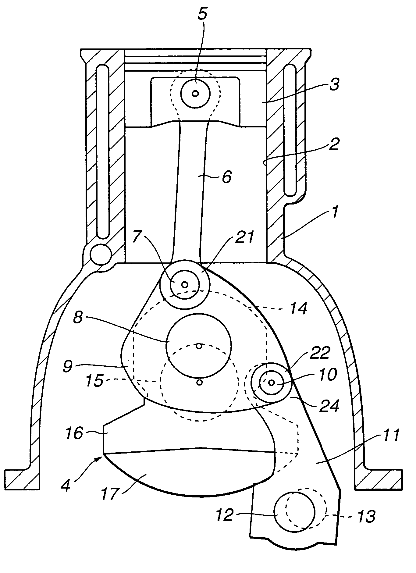
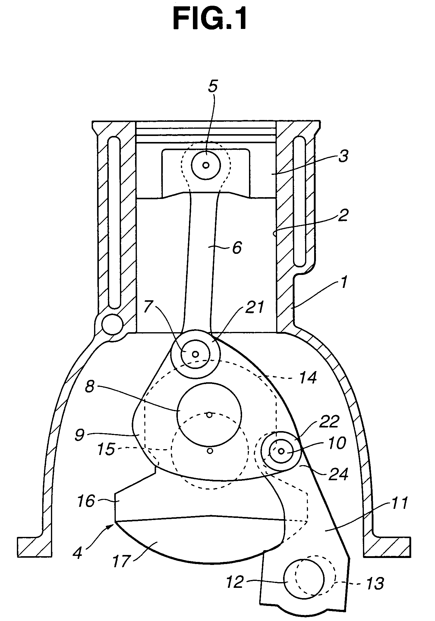
[0022]Referring to FIGS. 1–3, a multi-link piston crank mechanism of the present invention is explained. As illustrated in FIG. 1, an internal combustion engine includes cylinder block 1. Cylinder block 1 has a plurality of engine cylinders 2, only one of which is shown in FIG. 1. Piston 3 is slidably disposed in engine cylinder 2. Crankshaft 4 is rotatably supported by cylinder block 1.

[0023]Upper link 6 extends downward from piston 3. Upper link 6 has an upper end portion connected to piston 3 through piston pin 5. Upper link 6 has a lower end portion pivotally connected to an outer peripheral portion of lower link 9 through connection pin 7 hereinafter referred to as upper pin 7. Lower link 9 has a central portion pivotally disposed on crank pin 8 of crankshaft 4, and an outer peripheral portion connected to an upper end portion of control link 11 through connection pin 10 hereinafter referred to as control pin 10. Lower link 9 thus has two connecting portions at the outer periph...

second embodiment

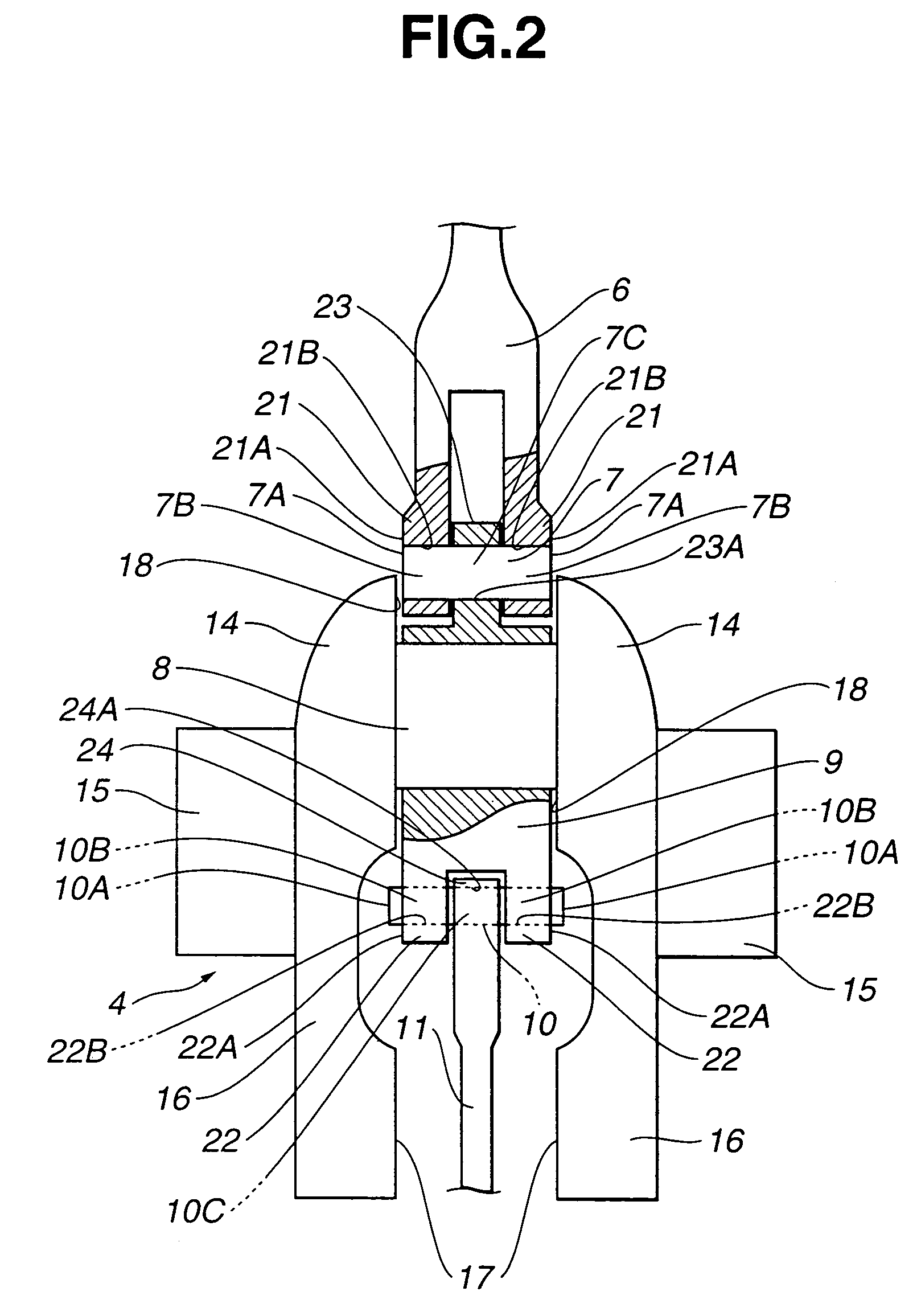
[0036]Referring to FIGS. 7A–7D, an operation of assembling the multi-link piston crank mechanism of the second embodiment will be explained hereinafter. First, as illustrated in FIG. 7A, piston 3, piston pin 5, upper link 6, upper pin 7 and one link part 9A of lower link 9 are coupled together. At this time, upper link 6 and one link part 9A are coupled to each other by merely inserting upper pin 7 into pin insertion holes 21B, 21B of upper link 6 and pin insertion hole 23A of one link part 9A. Subsequently, as shown in FIG. 7B, one link part 9A is placed on crank pin 8 while keeping the coupling state of piston 3, piston pin 5, upper link 6, upper pin 7 and one link part 9A. In this state, upper pin 7 is interposed between the pair of thrust surfaces 18, 18 of crank webs 14, 14. Axial displacement of upper pin 7 is thus limited by the mutual contact between end surfaces 7A, 7A and thrust surfaces 18, 18. Upper pin 7 is prevented from falling out of the space between thrust surfaces...


PUM


Abstract

A multi-link piston crank mechanism for an internal combustion engine, including a crankshaft having a crank pin, and crank webs connected with each other through the crank pin. A pair of thrust surfaces are formed on the crank webs so as to be opposed in a direction of a center axis of the crank pin. A first link pivotally supported on the crank pin is coupled to a second link through a connection pin located in a space between the thrust surfaces. The connection pin is moveable about the crank pin to form a circular trace along which the thrust surfaces extend. The end surfaces of the connection pin and the thrust surfaces come into mutual contact to prevent the connection pin from falling out of the space between the thrust surfaces.

Description

BACKGROUND OF THE INVENTION[0001]The present invention relates to a piston crank mechanism for reciprocating internal combustion engines having a crankshaft rotatable as a piston reciprocally moves. Specifically, the present invention relates to a multi-link piston crank mechanism in which a piston pin and a crank pin are connected with each other through a plurality of links.[0002]Japanese Patent Application First Publication No. 2002-188455 (corresponding to U.S. Pat. No. 6,561,142) discloses a multi-link piston crank mechanism useable as a variable compression ratio mechanism for reciprocating internal combustion engines. The multi-link piston crank mechanism includes upper and lower links linking a piston pin of a piston to a crank pin of a crankshaft, and a control link linking the lower link to an engine block. The upper and lower links are connected with each other so as to be relatively pivotally moveable about a connection pin. The lower link is pivotally supported on the c...

Claims


Application Information

Patent Timeline
Patent Type & Authority Patents(United States)
IPC IPC(8): F02B75/32F02B75/04F16C7/00F16C11/02F16H21/32
CPCF02B75/048F16C11/02F16H21/32
Inventor MOTEKI, KATSUYAIMADU, MASASHITAKAHASHI, NAOKIUSHIJIMA, KENSHI
Owner NISSAN MOTOR CO LTD
Why Eureka
Try Eureka