Method and apparatus for vibration welding of thermoplastic components

a technology of thermoplastic components and vibration welding, which is applied in the direction of lamination, building components, and lamination of the auxiliary device for lamination, can solve the problems of increasing the quantity of plastic flash created, and affecting the quality of extruded profiles. , to achieve the effect of improving the build-up of friction generated hea

Inactive Publication Date: 2006-10-17
BYSTRONIC MASCH
View PDF10 Cites 27 Cited by
  • Summary
  • Abstract
  • Description
  • Claims
  • Application Information

AI Technical Summary

Benefits of technology

[0031]The flat surfaces of the planar flange may incorporate a tex...

Problems solved by technology

As well as being a comparatively slow process, a further drawback of hot plate welding is that a large quantity of plastic flash is created at the weld line and this plastic flash has to be mechanically removed through a process that can involve cutting, shaving and routing operations.
Generally, the equipment required for flash removal is complex and expensive and the process can also damage any surface coatings applied to the extruded profiles.
In addition because the plastic flash material is contaminated during the welding process, the removed waste material cannot be recycled and the contaminated material can also effect the final weld strength.
Various efforts have been made in the past to use vibration welding techniques for plastic frame assembly but without...

Method used


Image

  • Method and apparatus for vibration welding of thermoplastic components
  • Method and apparatus for vibration welding of thermoplastic components
  • Method and apparatus for vibration welding of thermoplastic components

Examples


Embodiment Construction

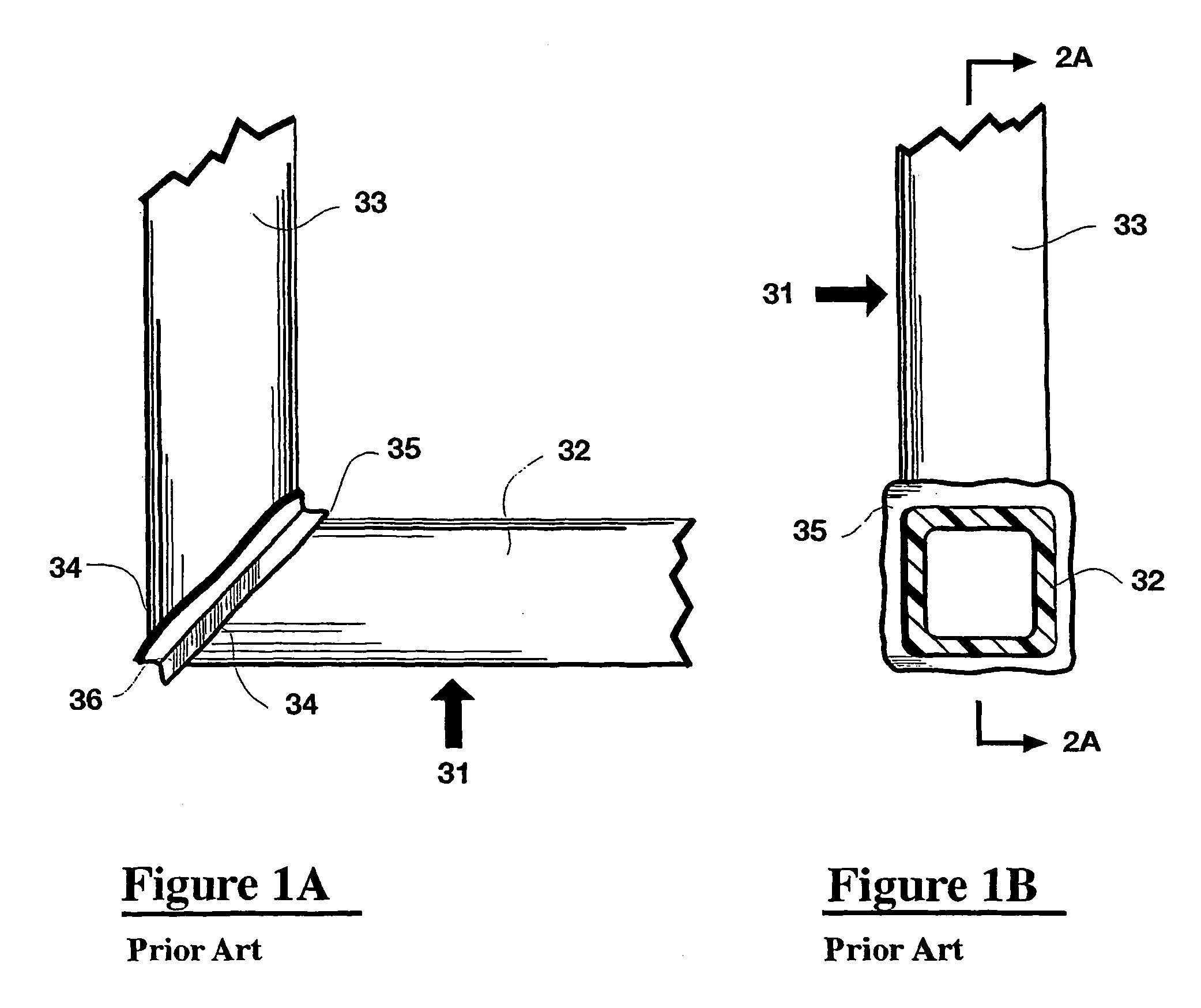
[0081]Referring to the drawings FIGS. 1A and 1B show side and front elevations of a frame corner assembly 31 fabricated from square hollow profile, glass fiber filled PVC extrusions 32 and 33. The miter cut corner ends 34 of the frame members 32 and 33 are welded together using conventional hot plate equipment. One major drawback of hot plate welding is that a large quantity of plastic flash 35 is created at the weld line 36. This plastic flash 35 has to be mechanically removed and this process often involves removing a shallow groove at the weld line 36. As a result of this mechanical removal process, the structural performance of the corner weld can be quite significantly reduced.

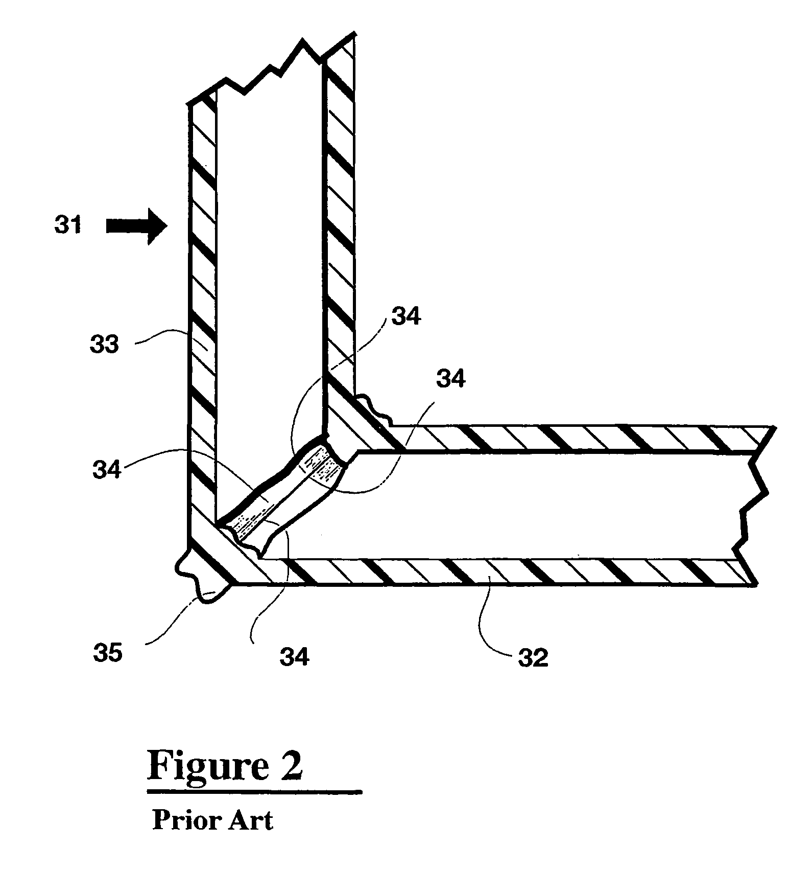
[0082]FIG. 2 shows a vertical cross section on a line 1B—1B through he frame corner assembly 31 where the miter cut ends 34 of the frame members 32 and 33 are welded together at the perimeter wall edge. As previously described this process creates plastic flash 35 that has to be mechanically removed from ...


PUM

PropertyMeasurementUnit
Thicknessaaaaaaaaaa
Thicknessaaaaaaaaaa
Angleaaaaaaaaaa

Abstract

Vibratory welded connections are formed between first and second members (32, 33) of thermoplastic material by interposing a junction piece (47) of similar material and vibrating the junction piece (47) at high speed while pressing the first second members (32,33) in a controlled manner against opposite sides of the junction piece (47). Friction created by the vibration generates heat which melts a small amount of material at the engaging surfaces which upon cooling provides a strong welded joint having minimal flash. Entire frame systems such as window-frames can be fabricated by an apparatus system (120) which forms a friction welded joint between adjacent ends of the frame members (134, 135, 136, 137). Furthermore the frame can be fabricated around a panel such as a glazing panel. The welded connections formed by the system do not mar the finish of the frame members and produce no unsightly flash bead requiring subsequent machining steps for its removal.

Description

CROSS REFERENCE TO RELATED APPLICATIONS[0001]This application is a National Phase Application of PCT / CA02 / 00842 filed on Jun. 7, 2002 claiming priority from Canadian Patent Application No. 2,349,795 filed Jun. 7, 2001.[0002]1. Field of the Invention[0003]This invention relates generally to assembly methods for thermoplastic components and more particularly to methods and apparatus for manufacturing window and door frames using vibration welding techniques.[0004]2. Background of the Invention[0005]At present, plastic window and door frames are typically assembled from polyvinyl chloride (PVC) extruded profiles using hot plate welding technology. Typically, the corner welding process involves pressing the mitered cut ends of two profiles against a Teflon-coated heated metal plate. After the thermoplastic PVC material has melted, the heated metal plate is removed and the two ends are then pressured against each other forming a hermetically sealed welded bond.[0006]Typically, in manufac...

Claims


Application Information

Patent Timeline
IPC IPC(8): B32B37/00B29C65/00B29C65/02B29C65/06B29C65/08B29C65/78E06B3/96
CPCB29C65/0618B29C66/9517B29C65/081B29C65/5057B29C65/7841B29C65/7844B29C66/1142B29C66/1162B29C66/21B29C66/322B29C66/324B29C66/5241B29C66/5243B29C66/52431B29C66/636B29C66/843E06B3/9608E06B3/968B29C65/0636B29C66/9513B29C65/4815B29C66/0044B29C66/8122B29C65/08B29C65/8207B29C66/3022B29C66/90B29C66/949B29C2045/4428B29C2793/009B29K2023/06B29K2027/06B29K2105/06B29K2309/08B29L2031/005B29L2031/778B29C65/483B29C65/00B29K2827/18B29C65/069B29C66/0042B29C66/71B29C66/7212B29C66/73921B29C66/72523B29C66/73111B29C66/73161B29C65/7802B29C48/12B29C48/0021B29C65/06
Inventor FIELD, STEPHENGLOVER, MICHAEL
Owner BYSTRONIC MASCH
Why Eureka
Try Eureka