Deposition profile modification through process chemistry

a technology of process chemistry and deposition profile, which is applied in the direction of chemical vapor deposition coating, coating, metallic material coating process, etc., can solve problems such as process expiration

Inactive Publication Date: 2006-10-17
NOVELLUS SYSTEMS
View PDF97 Cites 9 Cited by
  • Summary
  • Abstract
  • Description
  • Claims
  • Application Information

AI Technical Summary

Benefits of technology

[0008]This present invention addresses that need by providing methods for modifying the topography of HDP CVD films by modifying the composition of the reactive mixture. The methods allow for deposition profile control independent of film deposition rate. They rely on changes in the process chemistry of the HDP CVD system, rather than hardware modifica

Problems solved by technology
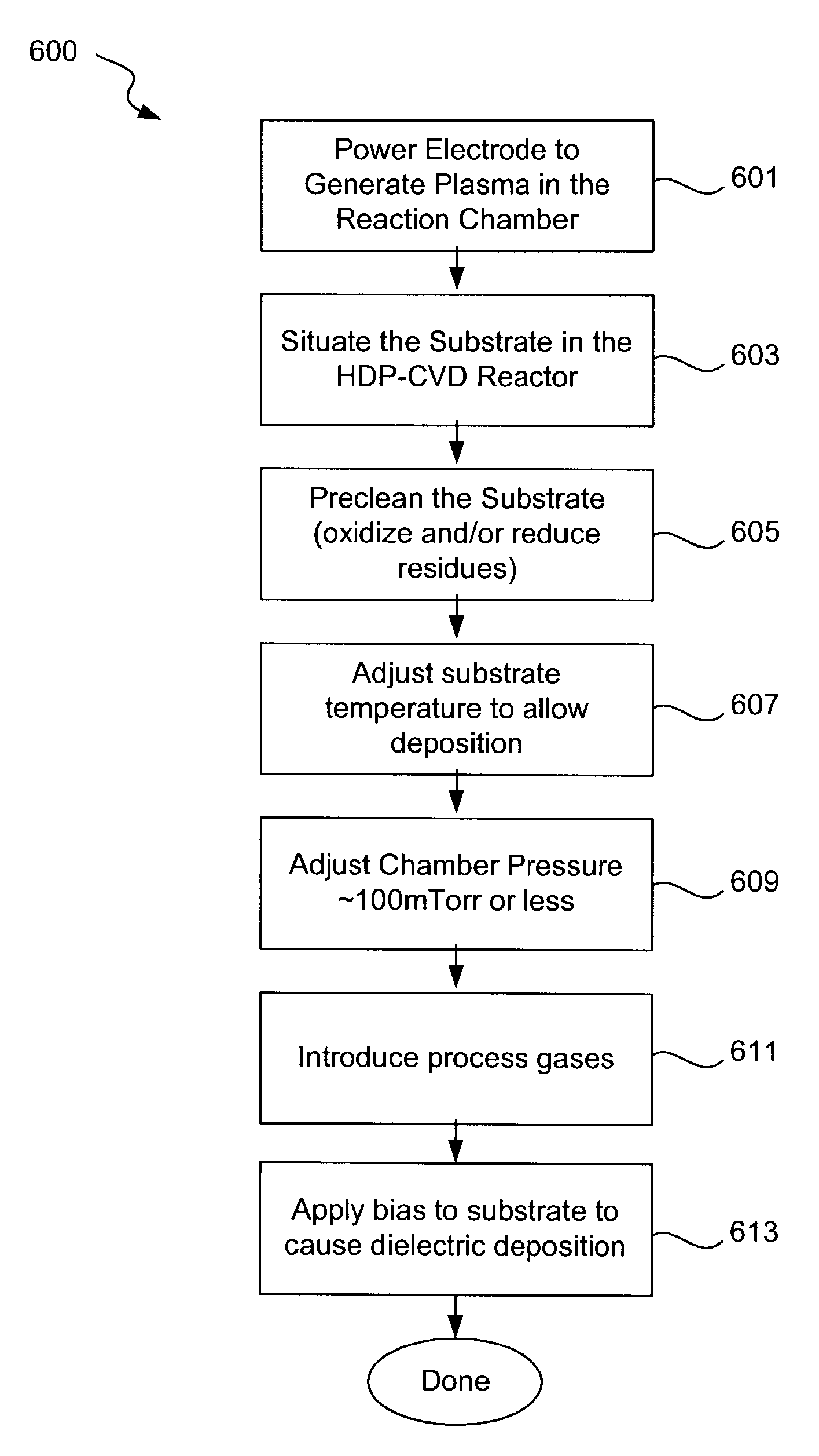
However, such processes are expiring due to incompatibility with th

Method used


Image

  • Deposition profile modification through process chemistry
  • Deposition profile modification through process chemistry
  • Deposition profile modification through process chemistry

Examples


example 1

Dielectric Optical Properties

[0091]FIG. 8 shows FTIR absorbance spectra for dielectric films deposited by a standard helium-based HDP CVD process (0 sccm H2 in the process gas) and a hydrogen containing process (1000 sccm H2 in the process gas). Importantly, all of the curves have peaks with almost identical spectral locations and magnitudes. This result indicates that the dielectric formed by a hydrogen-based process in accordance with the present invention has acceptable optical properties relative to the standard dielectric. Also, note the absence of Si—OH and Si—H bonds from the films, as well as the absence of adsorbed H2O.

example 2

Low wiw Uniformity Film Deposited Via Profile Superposition

[0092]FIG. 9 depicts a deposition map for a dielectric film deposited by profile superposition of complementary film layers. The maps bear contour lines indicating the deposition profile. The + and − signs indicate greater and less than average thickness, respectively. The film was deposited in two stages using different process conditions. In stage 1, 70% of the film was deposited using a helium-based chemistry and deposition conditions, as follows:

[0093]

SiH440sccmO274sccmHe490sccmH20sccmLF Power3000WattsHF Power2600Watts

[0094]In stage 2, 30% of the film was deposited using a hydrogen-based chemistry and deposition conditions, as follows:

[0095]

SiH440sccmO274sccmH21200sccmHe0sccmLF Power3000WattsHF Power2600Watts

[0096]The composite film produced by the combined profile superposition of the film layers produced by the helium- and hydrogen-based chemistries had a wiw uniformity of 1.3% 1σ.

example 3

Low wiw Uniformity Film Deposited Via H2 Addition

[0097]FIG. 10A depicts a deposition map for a dielectric film deposited by addition of hydrogen to a helium-based process chemistry during film deposition. The maps bear contour lines indicating the deposition profile. The + and − signs indicate greater and less than average thickness, respectively. The starting helium-based chemistry and conditions were as follows:

[0098]

SiH445sccmO256sccmHe490sccmH20sccmLF Power3200WattsHF Power800Watts

Hydrogen was gradually added until optimum wiw uniformity was achieved, as illustrated by FIG. 10B. The film produced had a wiw uniformity of about 1.3% 1σ.


PUM

PropertyMeasurementUnit
Temperatureaaaaaaaaaa
Fractionaaaaaaaaaa

Abstract

Disclosed are methods for modifying the topography of HDP CVD films by modifying the composition of the reactive mixture. The methods allow for deposition profile control independent of film deposition rate. They rely on changes in the process chemistry of the HDP CVD system, rather than hardware modifications, to modify the local deposition rates on the wafer. The invention provides methods of modifying the film profile by altering the composition of the reactive gas mixture, in particular the hydrogen content. In this manner, deposition profile and wiw uniformity are decoupled from deposition rate, and can be controlled without hardware modifications.

Description

BACKGROUND OF THE INVENTION[0001]This invention relates to electronic device fabrication processes and associated apparatus. More specifically, the invention relates to chemical vapor deposition processes for controlling the deposition profile of dielectric layers on semiconductor substrates.[0002]It is often necessary in semiconductor processing to deposit layers of dielectric. For example, blanket layers of dielectric are deposited and patterned to provide electrical isolation between vertical layers of semiconductor or conductor (e.g., metalization) in semiconductor devices (e.g., inter-layer dielectric (ILD) or inter-metal dielectric (IMD), as sacrificial protection layers during semiconductor processing, and to fill trenches to electrically isolate adjacent regions in a semiconductor device (e.g., shallow trench isolation (STI).[0003]In these semiconductor processing techniques, it is often necessary to control the deposition profile of dielectric material on the wafer. Dependi...

Claims


Application Information

Patent Timeline
IPC IPC(8): H01L21/31
CPCC23C16/401C23C16/45523C23C16/509H01L21/02164H01L21/02274H01L21/31612
Inventor PAPASOULIOTIS, GEORGE D.GOLDNER, EDITHGAURI, VISHALRAHMAN, MD SAZZADURSINGH, VIKRAM
Owner NOVELLUS SYSTEMS
Why Eureka
Try Eureka