Counter having improved counting speed

a counter and counting speed technology, applied in the field of counters, can solve the problems of increasing delay time and difficulty in determining the maximum frequency of the counter, and achieve the effect of widening the operational margin and reducing the delay time occurring

Inactive Publication Date: 2006-10-17
SAMSUNG ELECTRONICS CO LTD
View PDF7 Cites 5 Cited by
  • Summary
  • Abstract
  • Description
  • Claims
  • Application Information

AI Technical Summary

Benefits of technology

[0020]As described above, in synchronous and non-synchronous counters according to the present invention, it is possible to reduce

Problems solved by technology

Further, it is difficult to determine the maximum frequency of the counter 100 because of these combinational logic block

Method used


Image

  • Counter having improved counting speed
  • Counter having improved counting speed
  • Counter having improved counting speed

Examples


first embodiment

[0029]FIG. 5 is a block diagram of a circuit of a synchronous counter 500 according to the present invention. Referring to FIG. 5, the synchronous counter 500 includes first through N-th output signal generators 510, 520, 530, 530 and 540. ‘N’ is a natural number greater than 1, set to 4 for this description.

[0030]The first output signal generator 510 outputs a first output signal OUT1, which has a low level and a high level in each cycle of a clock signal CK, in response to the clock signal CK. The second output signal generator 520 outputs a second output signal OUT2, which has a low level and a high level in every two cycles of the clock signal CK, in response the clock signal CK and the first output signal OUT1. The third clock signal generator 530 outputs a third output signal OUT3, which has a low level and a high level in every four cycles of the clock signal CK, in response to the clock signal CK and the second output signal OUT2. The N-th output signal generator outputs an ...

second embodiment

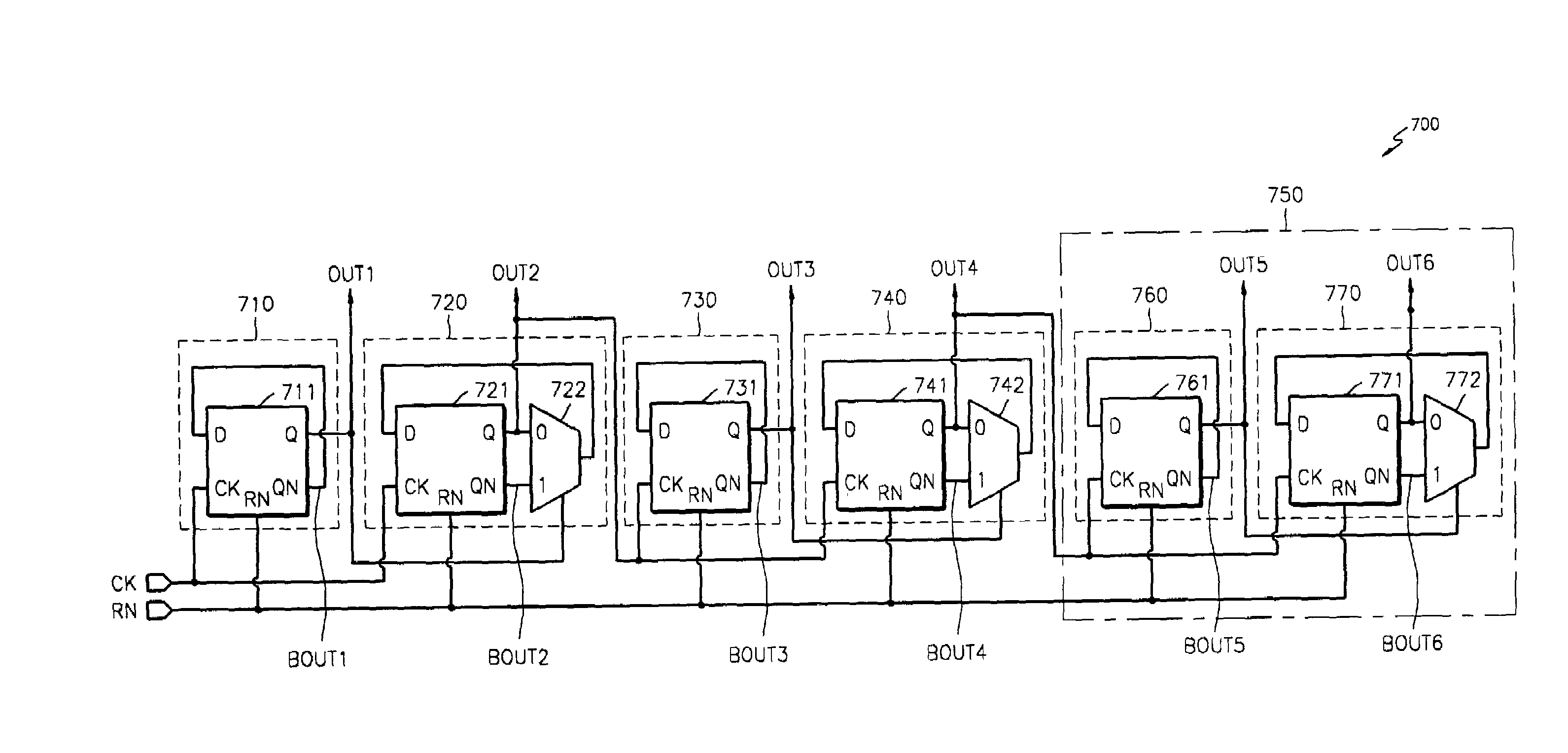
[0042]FIG. 7 is a block diagram of a circuit constituting a non-synchronous counter 700 according to the present invention. The counter 700 includes first through N-th output signal generators and N+1th through N+M-th output signal generators. N and M are natural numbers greater than 1, and for this description N is set to 2 and M is set to 2.

[0043]A first output signal generator 710 responds to a clock signal CK and outputs a first output signal OUT1 that has a low level and a high level once per cycle of the clock signal CK.

[0044]A second output signal generator 720 responds to the clock signal CK and the first output signal OUT1 and outputs a second output signal OUT2 which has a low level and a high level every two cycles of the clock signal CK.

[0045]A third output signal generator 730 responds to the second output signal OUT2 and outputs a third output signal OUT3 which has a low level and a high level once per cycle of the second output signal OUT2.

[0046]A fourth output signal...

third embodiment

[0063]Hereinafter, a synchronous counter according to the present invention will be described. The synchronous counter includes: a first output signal generator which responds to a clock signal, receives an inversion signal of a predetermined output signal and outputs the inversion signal as a first output signal; and second through N-th output signal generators which respond to the clock signal and an output signal generated by the preceding output signal generator and output predetermined second through Nth output signals (where N is a natural number greater than 1).

[0064]The first output signal generator includes a first flip flop which responds to the clock signal, outputs the inversion signal of the first output signal to an input terminal, and outputs the inversion signal as the first output signal.

[0065]Each of the second through Nth output signal generators includes 2N−2 flip flops connected together in the respective output signal generator, and a selecting means which resp...


PUM


Abstract

A counter having enhanced counting speed is provided. The counter includes first through N-th output signal generators. The first output signal generator responds to a clock signal and outputs a first output signal in which a low level and a high level are output once per cycle of the clock signal. The second output signal generator responds to the clock signal and the first output signal and outputs a second output signal in which a low level and a high level are output every two cycles of the clock signal. The third output signal generator responds to the clock signal and the second output signal and outputs a third output signal in which a low level and a high level are output every four cycles of the clock signal. The N-th output signal generator responds to the clock signal and the N−1th output signal and outputs an N-th output signal in which a low level and a high level are output every 2N−1 (where N is a natural number greater than 1) cycles of the clock signal. The first through N-th output signals represent logic values of an N-bit counter in which the first output signal is the least significant bit and the N-th output signal is the most significant bit. A synchronous or non-synchronous counter according to the present invention has reduced delay time, thereby ensuring a spacious operation margin in the design of peripheral circuits of the counter.

Description

BACKGROUND OF THE INVENTION[0001]1. Field of the Invention[0002]The present invention relates to a counter, and more particularly, to a counter having improved counting speed.[0003]2. Description of the Related Art[0004]As system-on-chip (SOC) systems have become faster, the core of each chip has been specially developed. In general, counters are used in most semiconductor devices and play an important role in determining delay between pipes. A short counter delay helps reduce the burden of combinational logic due to delay time, ensuring an operational margin in the design of the semiconductor circuit.[0005]FIG. 1 is a block diagram of a circuit of a general synchronous counter. Referring to FIG. 1, a synchronous counter 100 is set or reset in response to a reset signal RN and includes first through fourth flip flops 110, 120, 130, 140 and first and second combinational logic blocks 150 and 160 which operate in response to a clock signal CK. The first flip flop 110 receives an inver...

Claims


Application Information

Patent Timeline
IPC IPC(8): H03K23/40H03K23/00H03K23/58
CPCH03K23/58H03K23/588H03K23/00
Inventor JOO, KI-MO
Owner SAMSUNG ELECTRONICS CO LTD
Why Eureka
Try Eureka