Venetian blind mounted in double glazing unit and a sliding block therefor

a technology of double glazing and venetian blinds, which is applied in the direction of door/window protective devices, curtain suspension devices, wing arrangements, etc., can solve the problems of double glazing units, troublesome washing of contaminated curtains regularly, and contaminated curtains provided outside the window, etc., and achieves the effect of convenient operation and simple structur

Active Publication Date: 2006-10-24
CHANGSHU HIGH TECH CONSTR ENERGY SAVING TECH +1
View PDF13 Cites 41 Cited by
  • Summary
  • Abstract
  • Description
  • Claims
  • Application Information

AI Technical Summary

Benefits of technology

[0003]Accordingly, an object of the present is to provide a venetian blind provided in double glazing unit, lifting and deflecting of the leaves of the blind can be controlled at the same time

Problems solved by technology

However, the curtains provided outside the window tend to be contaminated and damaged, in addition, it is very trouble to wash the contaminated curtains regularly.
However, in the above double glazing units, since the blind is adjusted dire

Method used


Image

  • Venetian blind mounted in double glazing unit and a sliding block therefor
  • Venetian blind mounted in double glazing unit and a sliding block therefor
  • Venetian blind mounted in double glazing unit and a sliding block therefor

Examples


second embodiment

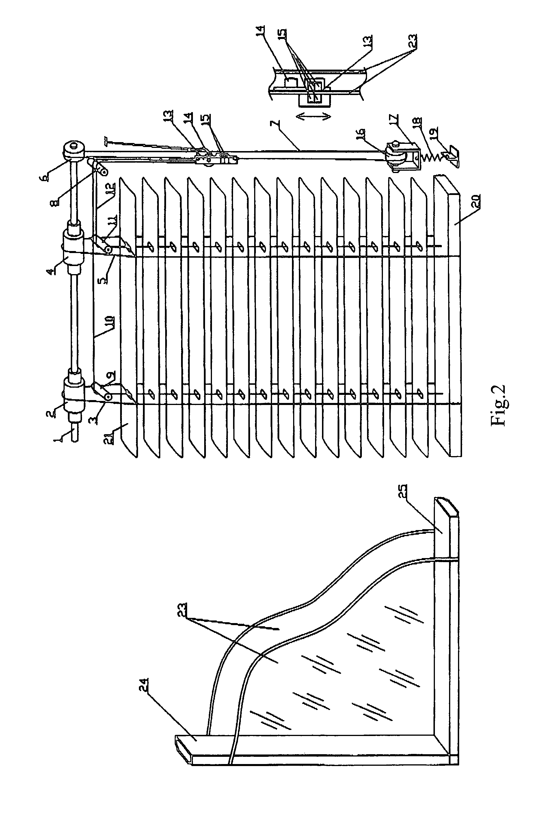
[0041]As shown in FIG. 3, by comparison with the second embodiment shown in FIG. 2, a pulley pull line 26 is provided additionally, and the form and mounting position of the magnet 15 and the winding manner of the turning pull line 7 are also different from that shown in FIG. 2. The turning tension pulley 16 functions to turn the direction and winding the pulley pull line 26. The magnet 15 does not reciprocate up and down but winds the pulley pull line 26 around the turning tension pulley 16 through rotation, so that the moveable pulley 14 and the pulley seat 13 are moved up and down by the pulley pull line 26 so as to lift and deflect the leaf of the blind.

[0042]In a same way as that of substituting the moveable pulley 14 and the pulley seat 13 in the second embodiment shown in FIG. 2 for the sliding block 22 in the first embodiment shown in FIG. 1, the moveable pulley 14 and the pulley seat 13 shown in FIG. 3 can be replaced by a slide block, and the one end of each of the lifting...

first embodiment

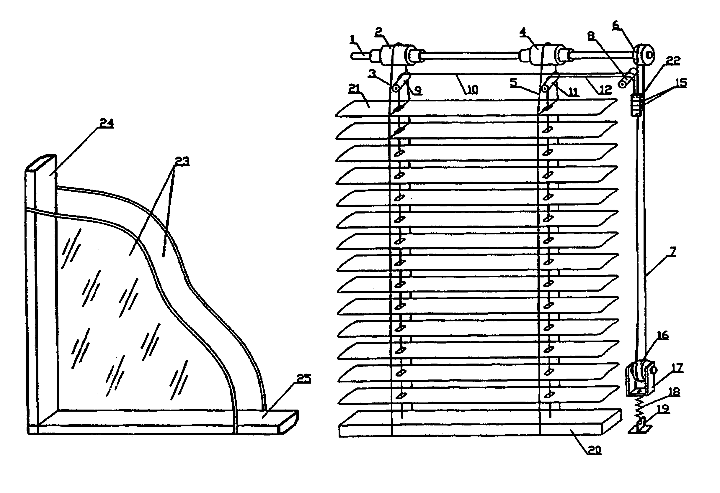
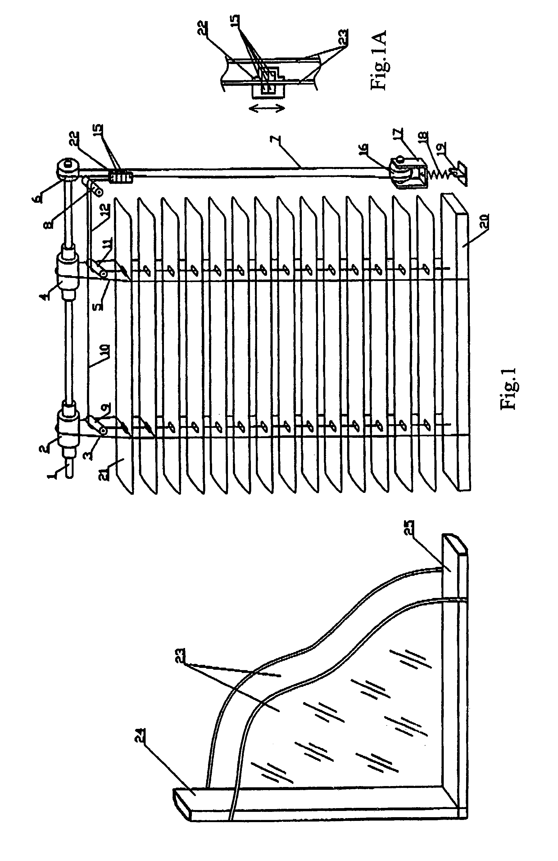
[0043]the sliding block 22 is described with reference to FIG. 1 and FIG. 4. As shown in FIG. 4, the sliding block 22 comprises a main body having substantively a U-shaped cross section, and two extension portions 26a and 26b extended outwardly from two sides of a U-shaped recess of the main body respectively, magnets 15 of the venetian blind are mounted in U-shaped recess of the main body. There are provided two first rollers 30a and 30b on a main surface A of the extension portions 26a and 26b, axial directions of the two first rollers 30a and 30b are substantively parallel to a width direction C of the extension portions 26a and 26b. Preferably, two first rollers 30a and 30b are symmetrical with respect to a transverse central line of said U-shaped recess along a length direction of the main body. There are also provided another two second rollers 31a and 31b on one side B of the extension portions 26a and 26b, axial directions of the second rollers are substantively perpendicula...


PUM


Abstract

A venetian blind provided in double glazing unit, which is mounted in a space defined by two sheets of glass, side frames, a top frame and a bottom frame, the venetian blind comprising a blind body composed of a counterweight, a long axis and a plurality of leaves, a driving unit, and two magnets, one of which being fixed to said sliding block and the other one being located outside the double glazing unit. The venetian blind could be lifted and deflect by the linear movement or rotation of the two magnets, one of which is inside the double glazing unit and the other one is outside the double glazing unit in the case that the double glazing unit is completely sealed. The venetian blind of the present invention is simple in structure and convenient for operating.

Description

TECHNICAL FIELD[0001]The present invention relates to a venetian blind, more particularly, to a venetian blind mounted in a double glazing unit, and the present invention also relates to a sliding block for the venetian blind provided in a double glazing unit.BACKGROUND ART[0002]For purpose of environmental protection and energy saving, the double glazing unit is widely used in the world because of its particular heat insulating performance, sound insulating performance, glazed frost proof, dust and pollution proof and so on, after more than one hundred year's development. For example, the related laws in Germany stipulate that all the buildings must adopt double glazed window, the conventional windows formed by general glass are forbidden. In North America regions, 95 percent of windows adopt double glazing. With the improvement of the standard of living, the double glazing is rapidly and widely developed in China in recent years. Since the double glazing is formed mainly by transp...

Claims


Application Information

Patent Timeline
IPC IPC(8): E06B3/50E06B9/264
CPCE06B9/264E06B2009/2646
Inventor JIN, RENZHEJIN, CHENGZHE
Owner CHANGSHU HIGH TECH CONSTR ENERGY SAVING TECH
Why Eureka
Try Eureka