Pipe cleaning kit

Inactive Publication Date: 2006-10-24
JADYDY EMYR
View PDF13 Cites 22 Cited by
  • Summary
  • Abstract
  • Description
  • Claims
  • Application Information

AI Technical Summary

Problems solved by technology

Manual cleaning of a large number of tube/fitting joint components can become t

Method used


Image

  • Pipe cleaning kit
  • Pipe cleaning kit
  • Pipe cleaning kit

Examples


Embodiment Construction

[0020]The present invention will now be described more fully hereinafter with reference to the accompanying drawings, in which preferred embodiments of the invention are shown. This invention may, however, be embodied in many different forms and should not be construed as limited to the embodiments set forth herein. Rather, these embodiments are provided so that this application will be thorough and complete, and will fully convey the true scope of the invention to those skilled in the art. Like numbers refer to like elements and prime notations refer to alternate elements throughout the figures.

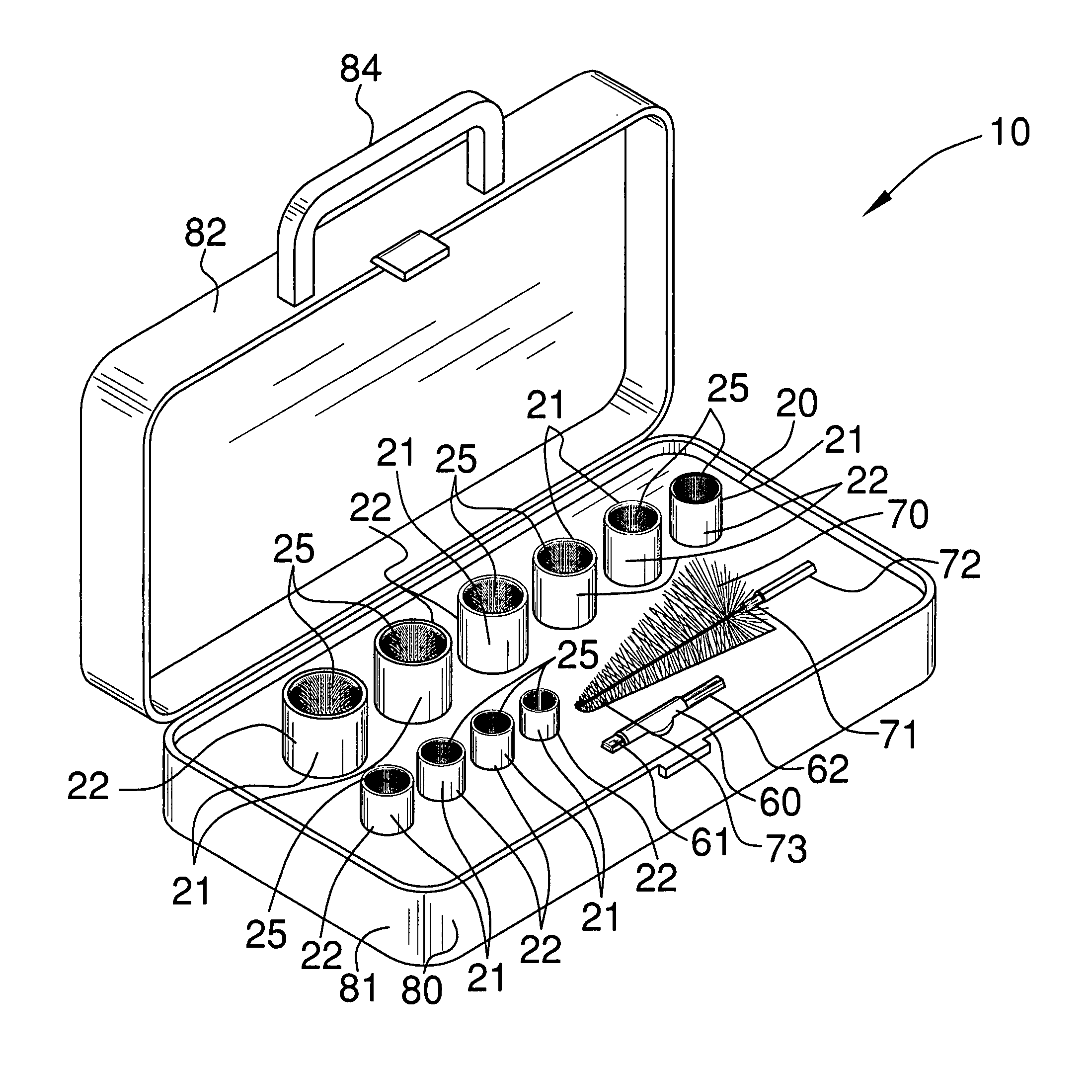
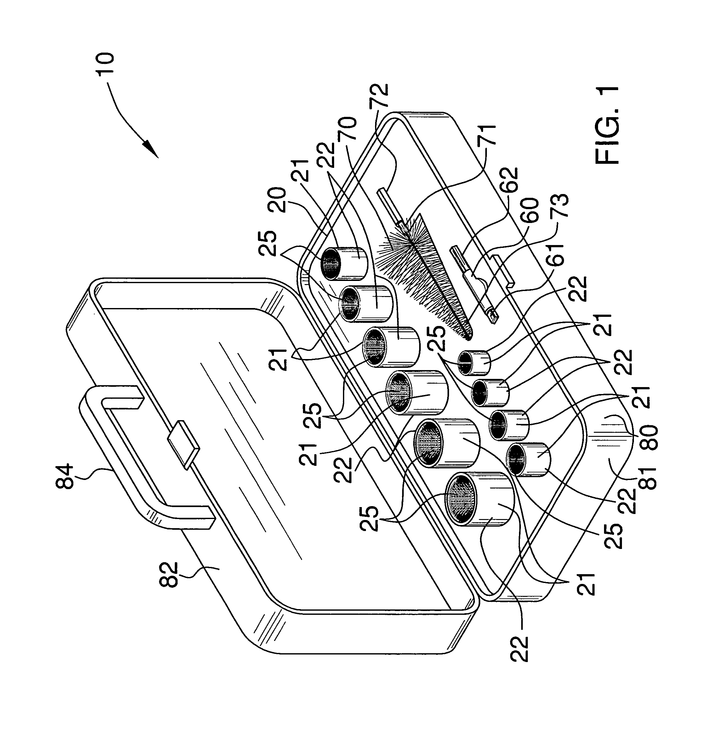
[0021]The assembly of this invention is referred to generally in FIGS. 1–6 by the reference numeral 10 and is intended to protect a pipe cleaning kit. It should be understood that the assembly 10 may be used to clean many different types of pipes and surfaces and therefore should not be limited to cleaning only copper pipes and associated fittings.

[0022]Referring initially to FIG. 1, the dev...


PUM

PropertyMeasurementUnit
Diameteraaaaaaaaaa
Shapeaaaaaaaaaa
Widthaaaaaaaaaa

Abstract

A cleaning kit operable by a tool for cleaning pipes and fittings to prepare same for soldering. The cleaning kit includes a plurality of sockets including wire bristles attached thereto and for receiving the outer surface of a pipe therealong. The plurality of pipes are maintain in continuous contact with a pipe surface for cleaning same while a tool rotatably engages the plurality of sockets about the pipe. The cleaning kit also includes a shank for receiving the plurality of sockets therein and for removably connecting to a tool respectively. A wire brush including a lower end portion and a second shank connected thereto is removably attachable to a tool so that the wire brush can rotatably engage an interior of a pipe and thereby clean same.

Description

BACKGROUND OF THE INVENTION[0001]1. Technical Field[0002]This invention relates to a pipe cleaning kit and, more particularly, to a rotatable tool-operated pipe-cleaning kit.[0003]2. Prior Art[0004]Soldering or brazing of pipe or tubing requires that the mating (or faying) surfaces of the pipe and fittings be thoroughly cleaned to present oxide-free and contaminant free surfaces which can be wetted by the molten solder or brazing alloy. This is required to form sound joints which are free of porosity and voids and which do not leak. Degreasing the joint components, if necessary, and then abrading the faying surfaces normally accomplish this.[0005]Degreasing is accomplished by wiping with a solvent appropriate for the oily contaminant to be removed. Oxides and dry contaminants are manually removed by rubbing with dry steel wool, emery cloth, or wire brushes. They may also be removed by using motor driven brushes or emery cloth. Proper cleaning of joint members prior to soldering or b...

Claims


Application Information

Patent Timeline
IPC IPC(8): B65D69/00
CPCB08B9/021B08B9/023
Inventor JADYDY, EMYR
Owner JADYDY EMYR
Why Eureka
Try Eureka