Cutting tool for rough and finish milling

a cutting tool and finishing technology, applied in the field of cutting tools, can solve problems such as rough workpieces, and achieve the effect of adding flexibility to the milling cutter

Inactive Publication Date: 2006-10-24
KENNAMETAL INC
View PDF27 Cites 42 Cited by
  • Summary
  • Abstract
  • Description
  • Claims
  • Application Information

AI Technical Summary

Benefits of technology

[0005]The inner finishing ring is designed for only abrasive material. This could be diamond, cubic boron nitride (CBN), or any other type of abrasive material. The inner finishing

Problems solved by technology

As a result, a workpiece can be rough and finish mi

Method used


Image

  • Cutting tool for rough and finish milling
  • Cutting tool for rough and finish milling
  • Cutting tool for rough and finish milling

Examples


Embodiment Construction

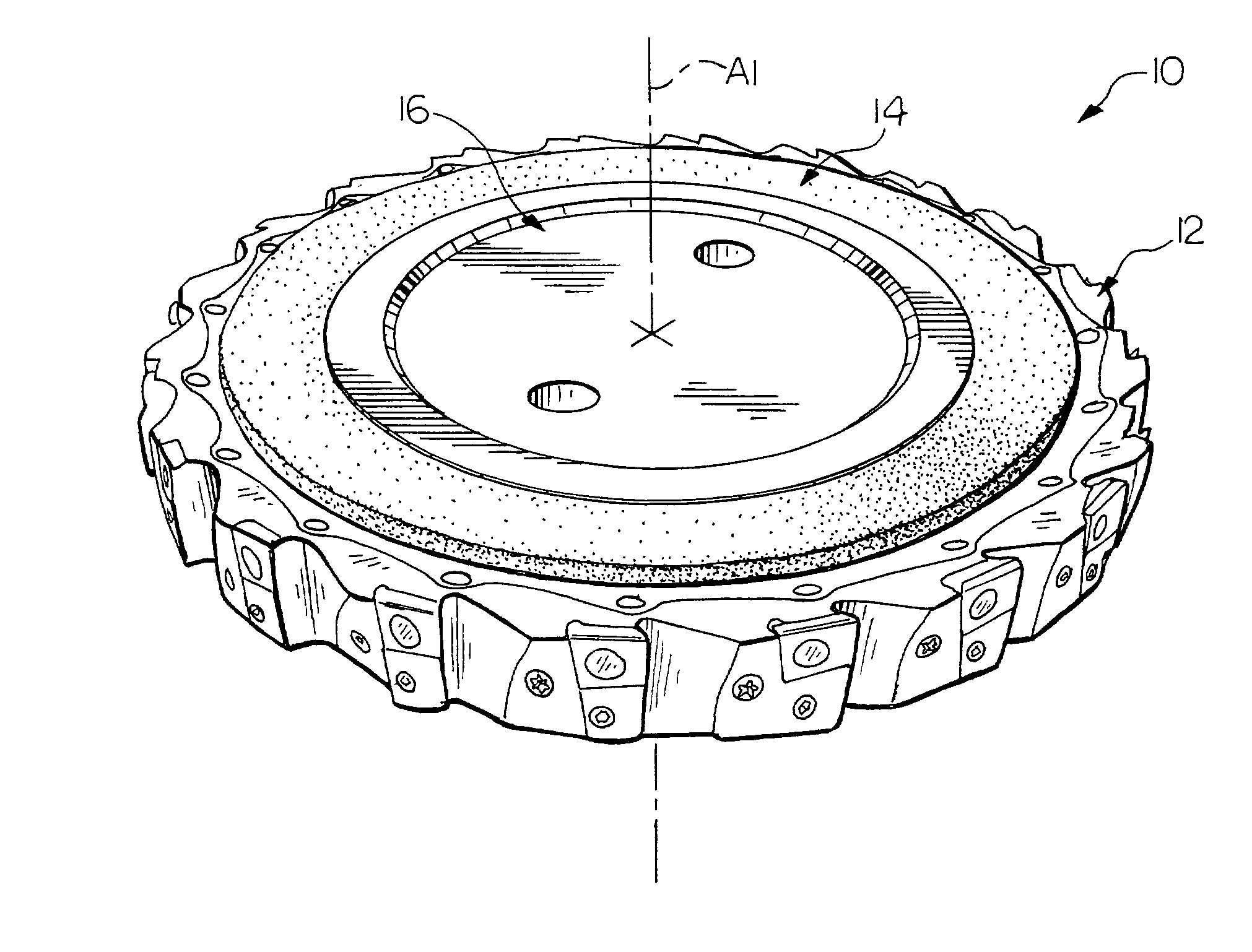
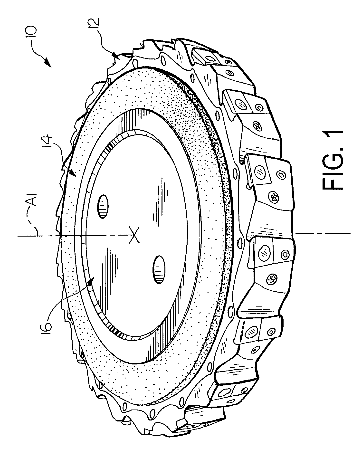
[0013]With reference now to FIG. 1, wherein like numerals designate like components throughout all of the several figures, there is illustrated a cutting tool according to a preferred embodiment of the invention. The cutting tool illustrated is in the form of a milling cutter 10 that functions to perform a rough milling operation and a finish milling operation in a single operation or pass. The milling cutter 10 is basically comprised of two concentric annular rings 12, 14. A first or outer ring, which is defined by a cutter body 12, is provided for the rough milling operations. A second or inner ring which is defined as a finishing ring 14, is provided for the finish milling operations. A shower cap 16 is provided at the center of the finishing ring 14 for directing coolant from a spindle (not shown) across the finishing ring 14 to clean the finishing ring 14 and flush chips produced from milling a workpiece away from the center of the milling cutter 10.

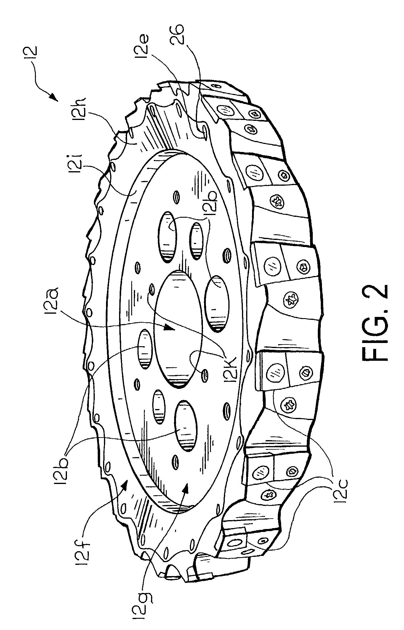
[0014]As illustrated in FIG....


PUM

PropertyMeasurementUnit
Pressureaaaaaaaaaa
Abrasiveaaaaaaaaaa
Circumferenceaaaaaaaaaa

Abstract

A milling cutter comprises a cutter body having two concentric annular rings. An outer ring is provided for rough milling and includes a plurality of cutting inserts equally spaced about the periphery of a cutter body. An inner finish ring comprises a ring member having a coating of abrasive material. As a result, a workpiece can be milled by a single milling cutter with the rough cutting inserts and then the abrasive material.

Description

FIELD OF THE INVENTION[0001]This invention generally relates to cutting tools and more particularly to a milling cutter for rough milling and finish milling in a single pass.BACKGROUND OF THE INVENTION[0002]Milling cutters for rough milling operations are well known. Such milling cutters typically comprise a cutter body, which is a generally circular shaped ring, having a plurality of pockets in an outer periphery thereof. A cutting insert is secured in each pocket. Each cutting insert comprises a body and at least one cutting edge. The body is secured directly in the pocket or to a cartridge, which is secured in the pocket. Similar milling cutters are known for finish milling operations. Such milling cutters have an abrasive material thereon, instead of having cutting inserts secured thereto. For milling a workpiece, the two milling cutters are used successively. After milling the workpiece with a rough milling cutter, the rough milling cutter is replaced with the finish milling cu...

Claims


Application Information

Patent Timeline
IPC IPC(8): B23C5/00B23C5/06B23C5/22B23C5/24B23C5/28B24D7/18
CPCB23C5/006B23C5/2472B24D7/18B23C5/06Y10T409/104929B23C2200/367B23C2220/605B23C2224/04B23C2226/125B23C2226/18B23C2226/31B23C2226/315Y10T407/1908Y10T407/14Y10T407/1904Y10T409/105247
Inventor SHEFFLER, GLENN W.
Owner KENNAMETAL INC
Why Eureka
Try Eureka