Device for loading a three-knife trimmer

a three-knife and trimmer technology, applied in the direction of stacking articles, thin material handling, metal working apparatus, etc., can solve the problems of insufficient time between two book blocks supplied for opening and closing the upper magazine intermediate shelf, and the performance of the known pre-stacking device is limited, so as to achieve a simple structure, high feed rate, and the effect of reducing the feed speed

Inactive Publication Date:
View PDF18 Cites 11 Cited by
  • Summary
  • Abstract
  • Description
  • Claims
  • Application Information

AI Technical Summary

Benefits of technology

[0006]It is the object of the present invention to provide a device for loading a three-knife trimmer with brochures, periodicals or like bound book blocks, which device makes possible a high feed rate, in particular for thin book blocks, while being of simple construction.
[0007]The book blocks to be trimmed can now be fed to the pre-stacking device in an imbricated formation even with a product thickness of less than the 5 mm. The transfer velocity, determined by the accelerator conveyor, of the book blocks to the magazine of the pre-stacking device can be limited to the velocity which is necessary to enable the book blocks reliably to reach the far side of the intermediate shelf. By holding back the following portion of the imbricated formation after the last book block in an imbricated flow section has been transferred to the magazine, a sufficient time window is provided for opening and closing the first, upper magazine intermediate shelf. In addition, the imbricated conveying results in lower and therefore more controllable feed velocities on the conveyor belts supplying the book blocks to the loading device, which conveyor belts, moreover, can be designed considerably shorter for the same conveying time (=required drying time).
[0008]With the advantage of an enlarged delivery surface for the book blocks to be accelerated, the accelerator conveyor includes an accelerator roller and at least one feed belt extending forwardly to the magazine. In a preferred embodiment the separating device is formed by a pressing roller arranged above the accelerator roller for onward conveyance of the leading portion of the imbricated formation, and by a separating finger arranged upstream of the pressing roller to hold back the following portion of the imbricated formation. To carry out the separating process the pressing roller and separating finger are lowered on to the imbricated flow, each bearing with a defined compressive force on the imbricated flow in the lowered separating position as a result of their movability relative to one another. It is thereby ensured that the next book block to be held back is intercepted by the separating finger while the pressing roller presses down the book block to be conveyed onward for secure engagement with the accelerator conveyor. As the separating device is raised the imbricated flow is released once more and is transferred into the magazine by the accelerator conveyor.
[0009]To count the book blocks conveyed in the imbricated flow a (laser) copy counter is preferably used, which counter is arranged upstream of the separating device, viewed in the feed direction, i.e. above the conveyor belt of the feed conveyor. The counting pulses of the copy counter are evaluated in a control device, while taking account of the feed velocity of the imbricated flow, to trigger the separating process. It has proved advantageous to hold down the imbricated book blocks on the front end of the accelerator conveyor with a spring-loaded pressing roller, whereby the book blocks are braced for reliable transfer to the magazine.
[0010]With the advantage of rapid actuation with regard to opening and closing, the first, upper magazine intermediate shelf is formed by two individual platforms located side-by-side in flush alignment, each individual platform consisting of fingers arranged in one plane and perpendicularly to a shaft, and the two shafts being driven in counter-rotation by a common drive, being rotated downwardly out of the magazine and then rotated back into same after a complete revolution. On the inward rotation the book blocks are in effect pressed downwardly into the lower magazine section while following book blocks are already being supplied once more.
[0011]The ejector, which is movable backwards and forwards by a separate drive, is suited not only to the counted stack mode but also, in particular, to the magazine mode. This is because, owing to the adjustability of the ejector stroke according to the height of the front trimming cut, format adjustments on the feed conveyor and in the stacking magazine are no longer required. An advantageous configuration of the movement profile is produced if the return stroke of the ejector is configured to be substantially diametrically opposed to the movement of a gripper of the intake device which receives the stack by its ejected end and withdraws it from the magazine. In effect, a third magazine intermediate shelf is thereby formed, which ensures that the following book blocks are not dragged forward on one side (magazine mode), or makes possible earlier discharge of stacks lying on the second magazine intermediate shelf (counted stack mode).

Problems solved by technology

The performance of the known pre-stacking devices is limited with regard to the processing of thin book blocks.
However, the counted stack mode requires book blocks to be individually fed, and individual feeding on conveyor belts can reliably execute a feed rate of only up to approx.
The delivery of the individually-supplied book blocks to the upper magazine section also becomes increasingly critical at this feed rate because the book blocks are thrown against the side wall of the magazine at excessive velocity.
In addition, the time between two book blocks supplied is no longer sufficient for opening and closing the upper magazine intermediate shelf to transfer the formed stack to the lower magazine section.

Method used


Image

  • Device for loading a three-knife trimmer
  • Device for loading a three-knife trimmer
  • Device for loading a three-knife trimmer

Examples


Embodiment Construction

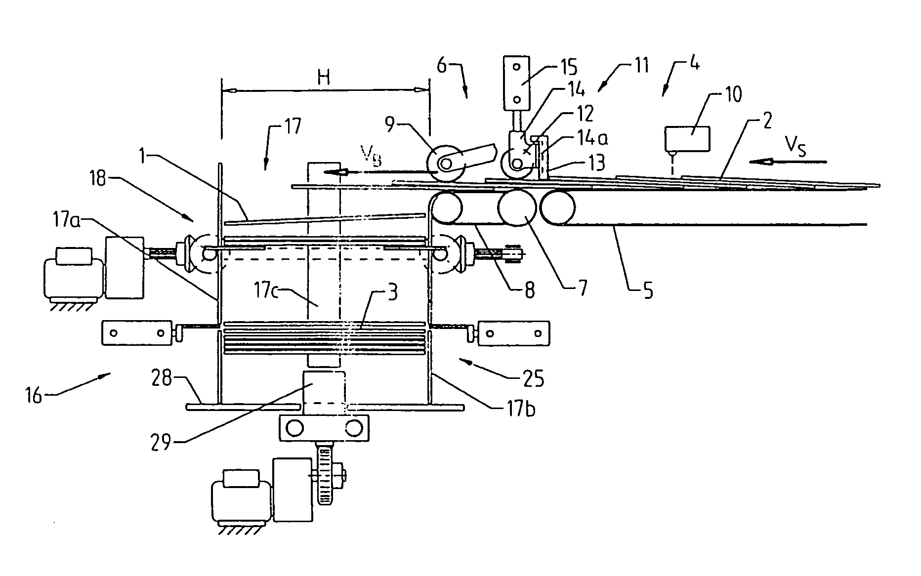
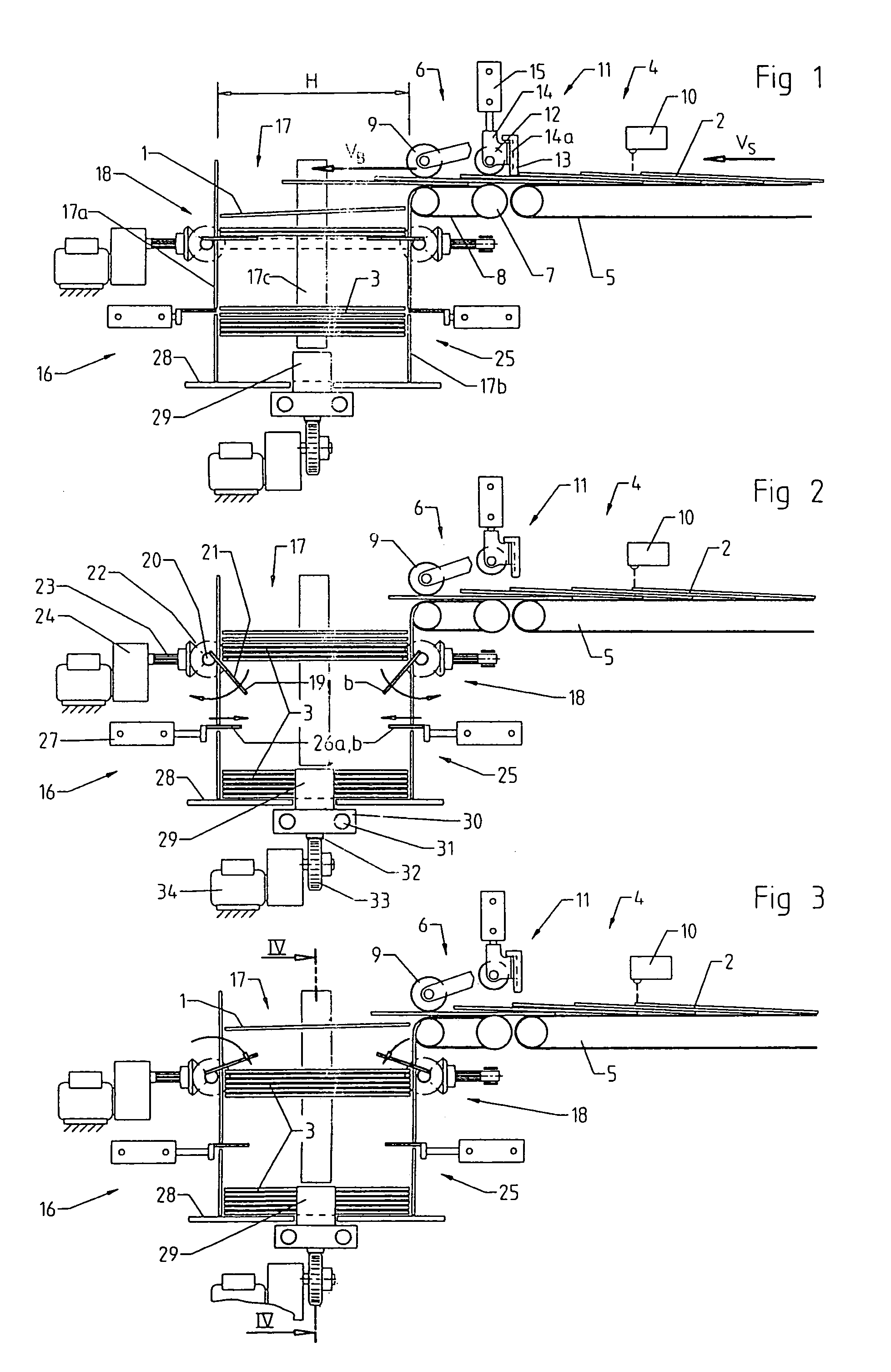
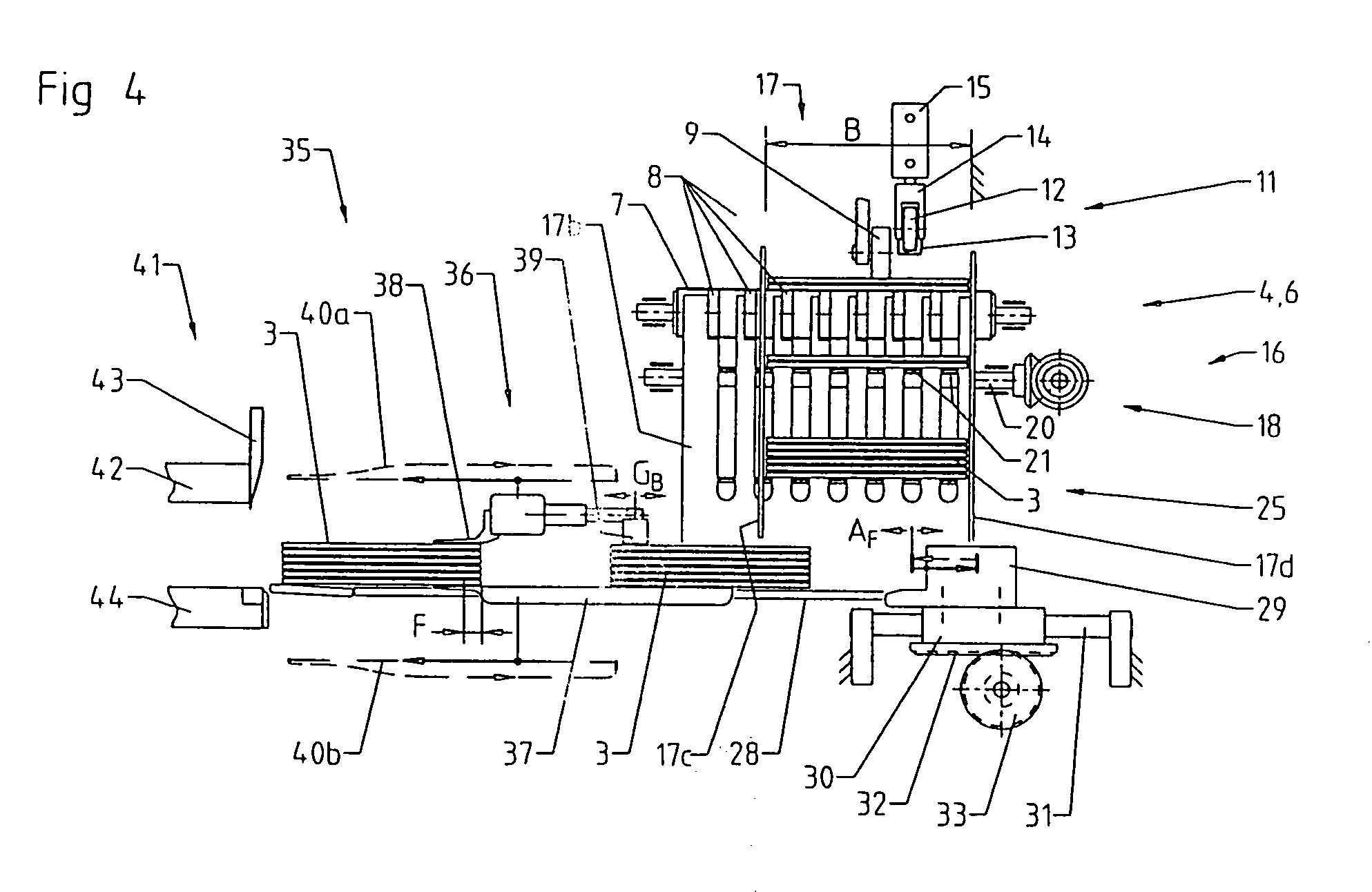
[0016]The loading device according to the invention comprises a feed conveyor 4, a stacking device 16, a delivery table 28 and an ejector 29, and is arranged upstream of the intake device 35 of a three-knife trimmer. The feed conveyor 4 is formed by a conveyor belt 5 driven continuously at a first velocity vS, and by an accelerator conveyor 6 located directly adjacent thereto in the feed direction and driven at a higher velocity vB.

[0017]The book blocks 1 to be trimmed are fed longitudinally with respect to their height H in an imbricated flow 2 to the stacking device 16, a following book block 1 in each case resting on the preceding book block 1. On reaching the accelerator conveyor 6, which consists of an accelerator roller 7 and a plurality of conveyor belts 8 arranged side-by-side, the book blocks are withdrawn from the imbricated flow 2 at the higher velocity vB and discharged into a magazine 17 of the stacking device 16, which magazine 17 is delimited by magazine side walls 17...


PUM

PropertyMeasurementUnit
stack heightaaaaaaaaaa
thickaaaaaaaaaa
thickaaaaaaaaaa

Abstract

In a device for loading a three-knife trimmer with brochures, periodicals or like bound book blocks (1), comprising a feed conveyor (4), a stacking device (16) operable in magazine mode and counted stack mode and including a magazine (17) having a first upper magazine intermediate shelf (18) and a second lower magazine intermediate shelf (25), and comprising a delivery table (28) arranged below said magazine (17) and an ejector (29) for cyclically and synchronously feeding a stack (3) of book blocks to the intake device (35) of the three-knife trimmer, it is provided that the feed conveyor (4) is formed by a conveyor belt (5) continuously driven at a first velocity (vS) and by an accelerator conveyor (6) located directly downstream thereof in the feed direction and driven at a higher velocity (vB), and that a separating device (11) for book blocks (1) supplied in an imbricated flow (2) is arranged in the transition zone from the conveyor belt (5) to the accelerator conveyor (6) for holding back a following portion of the imbricated flow, whereby a gap is created in the imbricated flow (2) for the opening and closing of the first magazine intermediate shelf (18). The device is characterised by its simple construction and makes possible a high feed rate, in particular for thin book blocks.

Description

BACKGROUND OF THE INVENTION[0001]The present invention relates to a device for loading a three-knife trimmer with brochures, periodicals or like bound book blocks.[0002]A three-knife trimmer is used for trimming the three non-bound edges of a book block, periodical or brochure. These products are thereby given their final format. The three-knife trimmer operates by means of side and front knives which cut diagonally against cutting rails according to the knife-edge and anvil principle, the three-side trimming being carried out in a trimming station. For this purpose the book blocks are fixed under pressure to the trimming table by a pressing ram and the side and front trimming is performed by phase-offset knife movements. The products can be processed singly or in a stack having a maximum stack height of up to 80 mm.[0003]The three-knife trimmer is frequently coupled in a conveyor line to an adhesive binding line or to a book production line. The products are fed automatically to an...

Claims


Application Information

Patent Timeline
Patent Type & Authority Patents(United States)
IPC IPC(8): B26D7/06B65H5/24B26D7/32B65H29/18B65H29/22B65H29/66B65H31/32B65H33/12
CPCB26D7/0675B65H29/18B65H29/22B65H29/6654B65H31/32B65H33/12B26D2007/0081B65H2301/4229B65H2301/515B65H2511/22B65H2513/21B65H2701/1932B65H2513/20
Inventor GREWE, HARALDSCHLOMP, KARSTENJUTERSONKE, GERHARD
Why Eureka
Try Eureka