Gas turbine engine variable vane assembly

a technology of variable vane and gas turbine engine, which is applied in the direction of machines/engines, liquid fuel engines, couplings, etc., can solve the problems of rotor performance loss, failure of bushings, and possible gas leakage paths within the vsv assembly, so as to facilitate the reduction of wear

Active Publication Date: 2006-10-24
GENERAL ELECTRIC CO
View PDF11 Cites 41 Cited by
  • Summary
  • Abstract
  • Description
  • Claims
  • Application Information

AI Technical Summary

Benefits of technology

[0006]In another aspect, a variable vane assembly for a gas turbine engine including a casing is provided. The variable vane assembly includes a variable vane and a retainer. The variable vane includes a radially inner spindle and a radially outer spindle. The radially inner and outer spindles are configured to rotatably couple the vane within the gas turbine engine. At least one of the radially inner and radially outer spindles includes at least one groove defined therein that includes at least one machined face. The retainer engages the groove at least one machined face to securely couple the variable vane within the gas turbine engine. The retainer is configured to facilitate reducing wear of the variable vane.
[0007]In a further aspect, a gas turbine engine is provided. The engine includes a rotor comprising a rotor shaft and a plurality of rows of rotor blades, a casing surrounding the rotor blades, and a variable vane assembly. The variable vane assembly includes at least one row of circumferentially spaced variable vanes and a retainer assembly. The at least one row of variable vanes is rotatably coupled to the casing and extends between an adjacent pair of the plurality of rows of rotor blades. Each of the variable vanes includes a radially inner spindle configured to rotatably couple the vane within the gas turbine engine. Each of the radially inner spindles includes at least one groove defined therein and having at least one machined face, the retainer assembly includes at least one retainer for engaging each spindle groove at least one machined face to securely couple each variable vane within the gas turbine engine. Each retainer is configured to facilitate reducing wear of each of the variable vanes.

Problems solved by technology

Over time, because only line-to-line sealing is defined between each pin and each variable vane, wear between the pins and variable vanes may cause possible gas leakage paths to develop within the VSV assembly.
Such leakage may result in failure of the bushing due to oxidation and erosion caused by high velocity high temperature air.
Furthermore, once the bushing fails, an increase in leakage past the variable vane occurs, which results in a corresponding rotor performance loss.
In addition, the loss of the bushing allows contact between the vane and the casing and / or inner shroud which may cause wear and increase the engine overhaul costs.

Method used


Image

  • Gas turbine engine variable vane assembly
  • Gas turbine engine variable vane assembly
  • Gas turbine engine variable vane assembly

Examples


Embodiment Construction

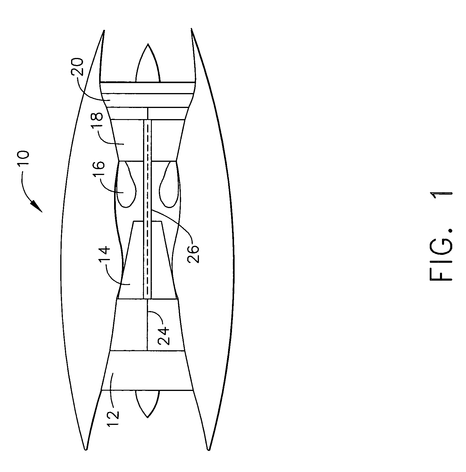
[0012]FIG. 1 is a schematic illustration of a gas turbine engine 10 including a low pressure compressor 12, a high pressure compressor 14, and a combustor 16. Engine 10 also includes a high pressure turbine 18 and a low pressure turbine 20. Compressor 12 and turbine 20 are coupled by a first shaft 24, and compressor 14 and turbine 18 are coupled by a second shaft 26. In one embodiment, the gas turbine engine is a CF6 available from General Electric Company, Cincinnati, Ohio.

[0013]In operation, air flows through low pressure compressor 12 and compressed air is supplied from low pressure compressor 12 to high pressure compressor 14. The highly compressed air is delivered to combustor 16. Airflow from combustor 16 drives turbines 18 and 20 before exiting gas turbine engine 10.

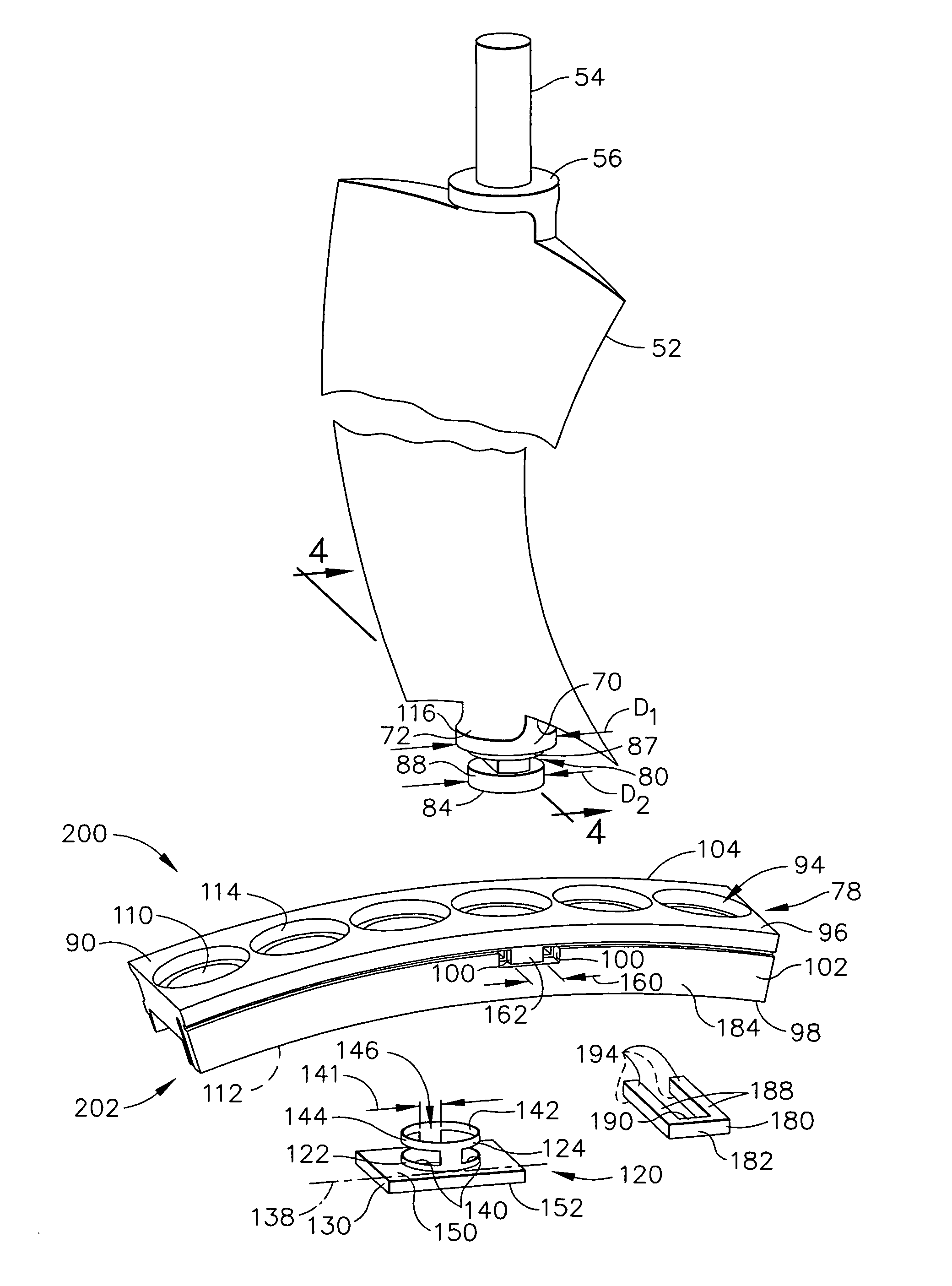
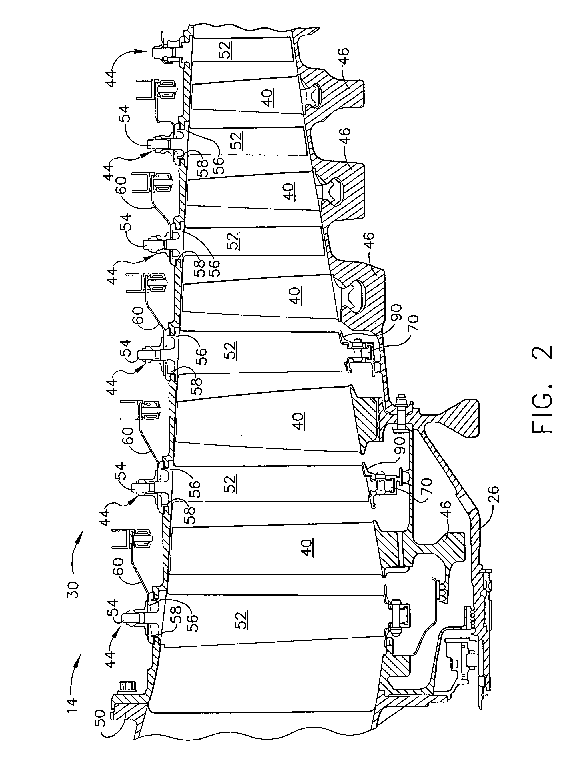
[0014]FIG. 2 is partial enlarged schematic view of a gas turbine engine rotor assembly 30, such as compressor 14. FIG. 3 is an enlarged exploded view of a variable stator vane assembly 44 that may be coupled withi...


PUM


Abstract

A method facilitates assembling a variable vane assembly for a gas turbine engine including a casing and an inner shroud. The method comprises providing at least one variable vane including a radially inner spindle that includes a groove defined therein that has at least one machined face, and coupling the variable vane radially between the casing and the inner shroud such that at least a portion of the radially inner spindle is inserted at least partially through an opening extending radially through the inner shroud. The method also comprises securing the variable vane to the inner shroud by engaging the spindle machined face with a retainer coupled to the inner shroud.

Description

BACKGROUND OF THE INVENTION[0001]This invention relates generally to gas turbine engines, and more specifically to variable stator vane assemblies used with gas turbine engines.[0002]At least some known gas turbine engines include a core engine having, in serial flow arrangement, a fan assembly and a high pressure compressor which compress airflow entering the engine, a combustor which burns a mixture of fuel and air, and low and high pressure turbines which each include a plurality of rotor blades that extract rotational energy from airflow exiting the combustor. At least some known rotor assemblies, such as a high pressure compressors', include a plurality of rows of circumferentially spaced rotor blades, wherein adjacent rows of rotor blades are separated by rows of variable stator vane (VSV) assemblies. More specifically, a plurality of variable stator vane assemblies are secured to casing extending around the rotor assembly and wherein each row of VSV assemblies includes a plur...

Claims


Application Information

Patent Timeline
Patent Type & Authority Patents(United States)
IPC IPC(8): F01D17/12F01D9/04F01D17/16F01D25/24F03B1/04F04D29/56
CPCF01D17/162F04D29/563Y10T403/587F16B2200/71
Inventor CORMIER, NATHAN GERARDBOWEN, WAYNE RAYRHODA, JAMES EDWINHEADLEY, MITCHELL JAY
Owner GENERAL ELECTRIC CO
Why Eureka
Try Eureka