Rapid prototyping apparatus and method of rapid prototyping

a rapid prototyping and prototyping technology, applied in the field of rapid prototyping apparatus, can solve the problems of limiting the potential of making details in the prototype, affecting the quality of the prototype, so as to achieve simple technique, increase power input, and high solution

Inactive Publication Date: 2006-10-31
3D SYST INC +1
View PDF14 Cites 73 Cited by
  • Summary
  • Abstract
  • Description
  • Claims
  • Application Information

AI Technical Summary

Benefits of technology

[0031]Yet another advantage of the invention is that it gradually becomes possible to obtain increased power inputs from e.g. lamps in the UV-area resulting in the effect transmitted to the light valves being so great that the individual light guides may emit a light that has sufficient energy to illuminate more light valves simultaneously.
[0032]In connection with the use of e.g. UV lamps, it has also turned out that the introduction of “macro illumination areas”, i.e. areas illuminated by one single optical fiber per area, does not result in any significant edge effects between each illumination area, just as it has turned out that potential and significant variations between the emitted effects from each light guide (resulting from a varying intensity profile of a connected lamp e.g. due to various placings of the coupling optics and the individual fibers in relation to the lamp) may be compensated for by a suitable mix of the light guides whereby the result of the illumination is a homogenous visual impression without any significant differences in intensity in the edge areas.
[0033]The above-mentioned mix may e.g. be carried out in relation to the adjacent macro illumination areas that may be provided with an optical effect which does not vary significantly while macro illumination areas situated relatively far from each other may vary in intensity without resulting in significant visual interruptions on the illumination surface.
[0034]An additional advantage, according to the invention, is that it is possible to filtrate light emitted to or from the individual optical fibers so that the illumination intensity is homogenous for all or a part of the optical fibers.
[0035]According to the invention, an apparatus like this may be based on a relatively simple technique compared to the existing techniques while also creating a high solution, high illumination speed, good precision properties and a uniform illumination intensity over a very large illumination area.
[0036]The invention is particularly advantageous in relation to light valves associated with a relatively great loss. An example of such light valves may e.g. be spatial light modulators such as LCD, PDLC, PLZT, FELCD and Kerr cells. Other types of light valves may e.g. be electromechanical reflection-based light valves of the DMD type.

Problems solved by technology

However, according to the optical laws, prolonged light sources alone only provide the opportunity to create a prolonged point of illumination which, in turn, significantly limits the potential of making details in the prototype.
Apart from that, prolonged light sources are subject to relatively large losses.

Method used


Image

  • Rapid prototyping apparatus and method of rapid prototyping
  • Rapid prototyping apparatus and method of rapid prototyping
  • Rapid prototyping apparatus and method of rapid prototyping

Examples


Embodiment Construction

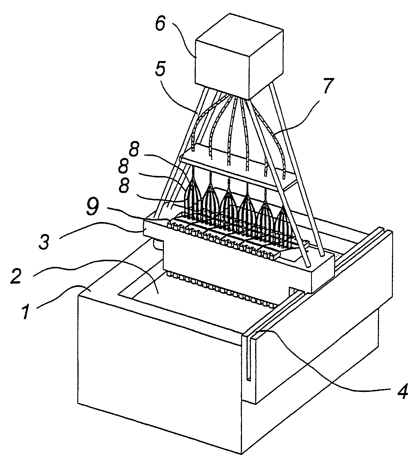
[0064]FIG. 1 shows a schematic diagram of an embodiment according to the invention.

[0065]Microshutters or light valves are defined in the broadest sense as transmissive light blinders that may e.g. be made of micromechanical shutters. The individual shutter elements may e.g. be of the type described in the French patent application No. 9412928 or the type described in the corresponding EP-A 709 706 as the preferred embodiment of the invention deems it decisive that the light to be modulated is transmitted directly through the individual microshutters in order to create a minimal loss of transmission.

[0066]The shown Rapid Prototyping (RP) apparatus comprises a stationary part whose most significant component consists of a container 1 designed to contain a suitable amount of liquid RP material 2. An RP material is the material of which the RP prototype will be made such as epoxy, acrylates or other RP materials. In addition, the stationary part is designed with a leader 4 which can be...


PUM

PropertyMeasurementUnit
mutual distanceaaaaaaaaaa
distanceaaaaaaaaaa
optical energyaaaaaaaaaa

Abstract

The invention relates to a rapid prototyping apparatus for the manufacturing of three dimensional objects by additive treatment of cross sections comprising a wholly or partially light-sensitive material, said apparatus comprising at least one light source for illumination of a cross section of the light-sensitive material by at least one spatial light modulator of individually controllable light modulators, wherein at least one light source is optically coupled with a plurality of light guides arranged with respect to the spatial light modulator arrangement in such a manner that each light guide illuminates a sub-area of the cross section.
According to the invention, it is possible to obtain a significant simplification of an RP design system, just as the apparatuses designed are essentially capable of creating prototypes of any size, according to the invention.

Description

TECHNICAL FIELD[0001]The invention relates to a so-called rapid prototyping apparatus for the manufacturing of three dimensional objects by additive treatment of cross sections, said cross sections consisting of a wholly or partially light-sensitive material, said rapid prototyping apparatus comprising at least one light source.[0002]The invention also relates to a method of manufacturing of three dimensional objects by means of a rapid prototyping apparatus wherein a wholly or partially light-sensitive material is treated by means of illumination of a cross section of the material by at least one spatial light modulator arrangement of controllable light modulators.BACKGROUND OF THE INVENTION[0003]In connection with the manufacturing of mechanical prototypes, and especially during the production design processes, recent years have introduced various types of rapid prototyping techniques (RP) where three dimensional objects are manufactured by sequential cross section layers generate...

Claims


Application Information

Patent Timeline
Patent Type & Authority Patents(United States)
IPC IPC(8): B29C35/08B29C67/00
CPCB29C67/0066B29K2995/0073B29C64/135B33Y10/00B33Y30/00
Inventor HENNINGSEN, HENNING
Owner 3D SYST INC
Why Eureka
Try Eureka