Laminar-vortex welding chamber

a technology of vacuum chamber and vacuum chamber, which is applied in the direction of non-electric welding apparatus, welding apparatus, manufacturing tools, etc., can solve the problems of inability to welded exotic metals such as titanium in the presence of air without producing weak and discolored welds, high cost, and high labor intensity, and achieve air tight seals and prevent the introduction of ambient air

Inactive Publication Date: 2006-10-31
CORNE JOSEPH E
View PDF8 Cites 23 Cited by
  • Summary
  • Abstract
  • Description
  • Claims
  • Application Information

AI Technical Summary

Benefits of technology

[0008]The present invention is a rigid-bodied welding chamber comprising a transparent dome that covers an open top-side of a rigid generally rectanguloid enclosure. One edge of the dome is hinged to one side of the enclosure such that the dome may assume either an open position, providing access to the interior of the enclosure, or a closed position, thereby achieving a substantially air-tight seal between the dome and the enclosure. The dome includes a one-way vent for discharging ambient air from within the chamber while preventing the introduction of ambient air into the chamber.

Problems solved by technology

Many exotic metals, such as titanium, cannot be welded in the presence of air without producing a weak and discolored weld.
A major problem with the beach-ball type of chamber is its susceptibility to damage from a hot torch, from weld spatter, or from sharp-edged workpieces, any of which may cause holes that allow the escape of inert gas or the entry of air.
Costly downtime is the result until the damaged area is patched.
Secondly, rips in the plastic may occur in the creases caused by repeated inflations and deflations.
Thirdly, pockets of air residing the in the folds of such a chamber when deflated can mix with incoming inert gas, increasing the time required to fully purge such a chamber.
Lastly, it is difficult to clean such a soft plastic chamber without it becoming scratched, which impedes viewing therethrough during subsequent operation by a user.
One problem with this type of device is its limited visibility through what is typically a small window.
Secondly, if the door is located on the top of the chamber, it is difficult to add or remove workpieces, if the door is on the side of the chamber, inert gas is lost when the chamber is opened.
Thirdly, the inside square edges and corners can trap pockets of air, increasing purge time and making cleaning relatively difficult.
Workpieces are placed on or removed from the table by lifting the dome, resulting in a complete loss of gas.
First is the expense, as many companies find such a device cost-prohibitive.
Secondly is the often impractical weight of such a device.
Thirdly, the right-angle juncture of the dome and the table leaves pockets of air.
The device uses a diffuser to slow the entry of gas to prevent any turbulence, thereby inhibiting any scrubbing action of residual pockets of air within the device, resulting in longer purge times.

Method used


Image

  • Laminar-vortex welding chamber
  • Laminar-vortex welding chamber
  • Laminar-vortex welding chamber

Examples


Embodiment Construction

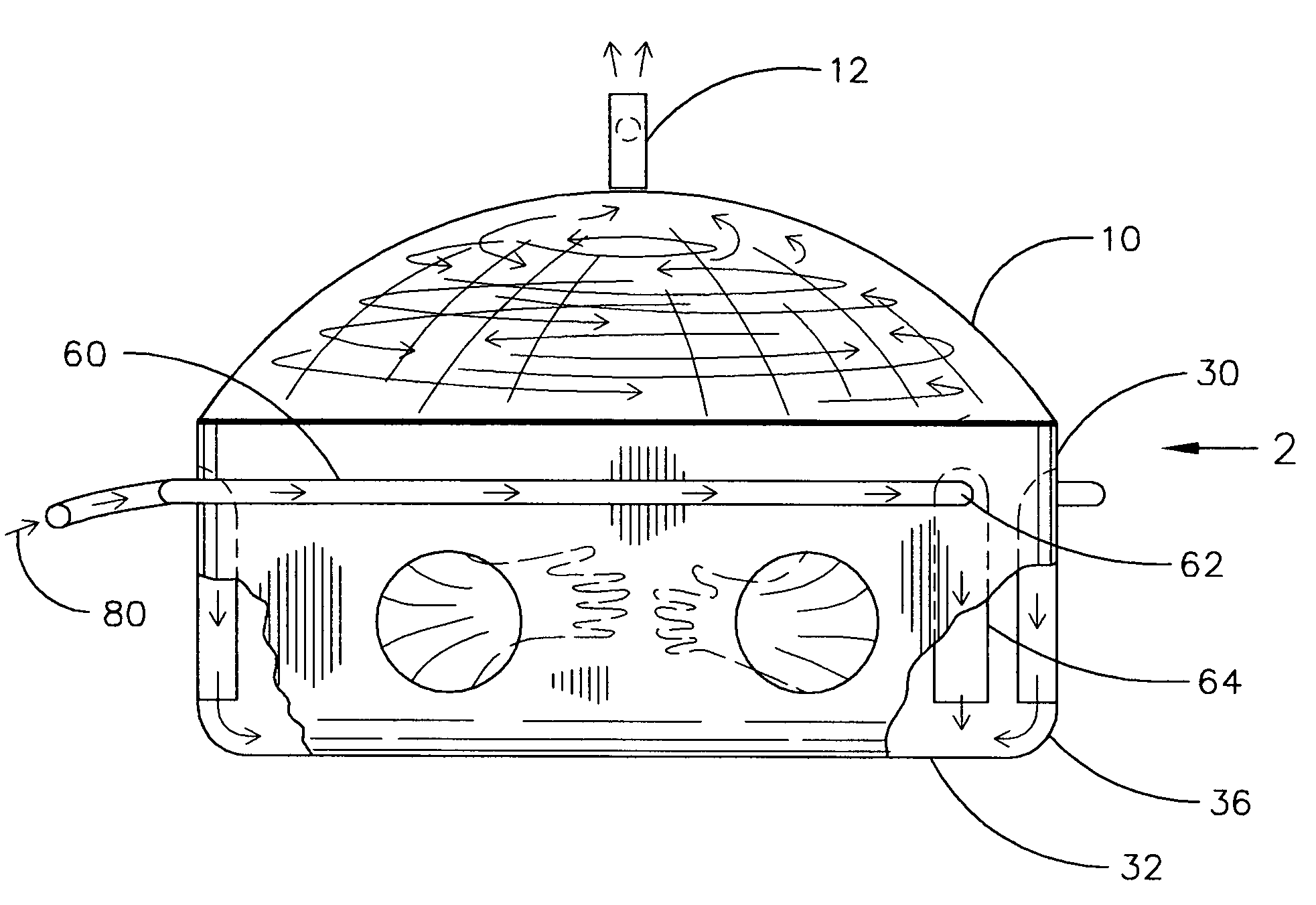
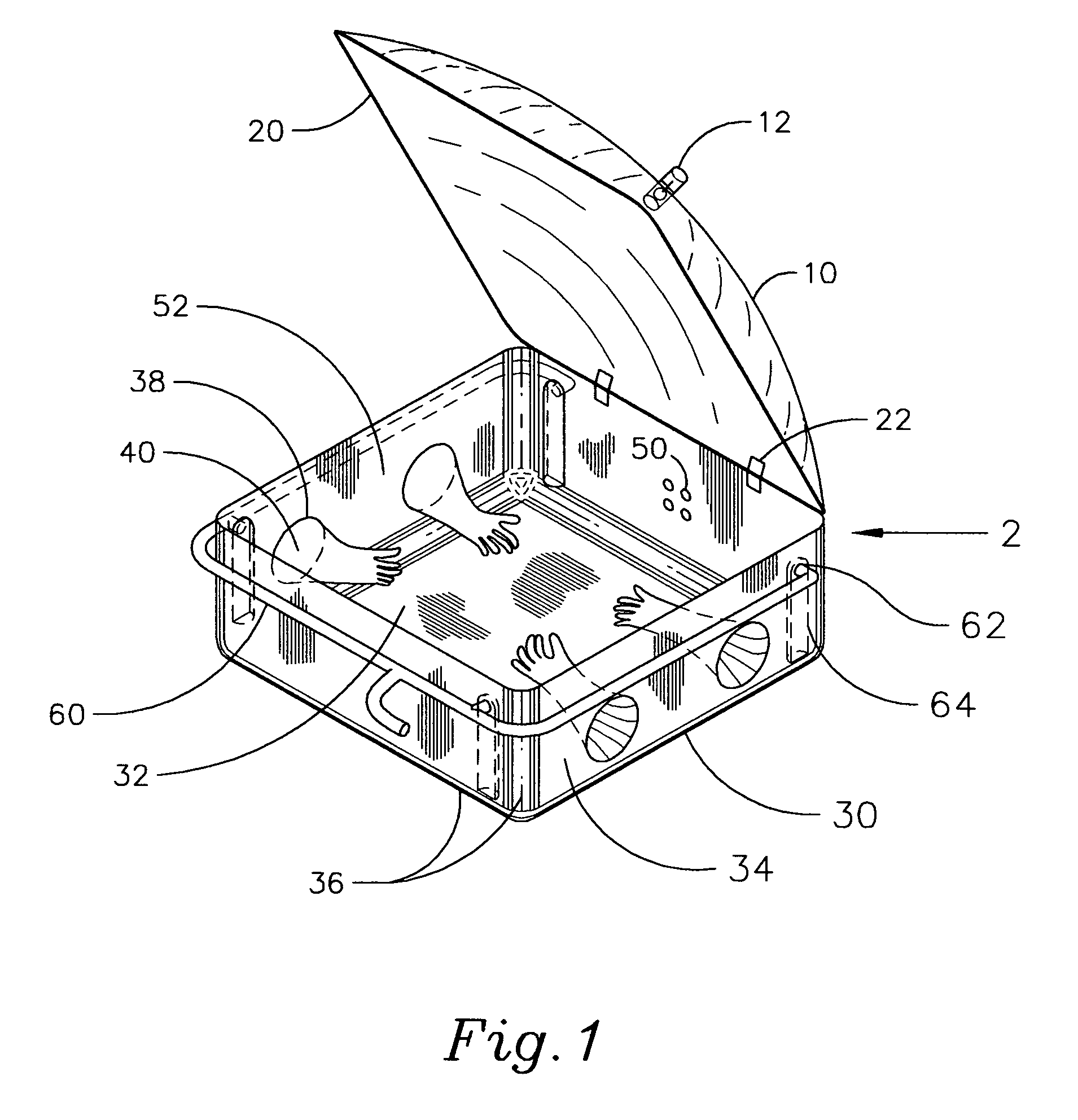
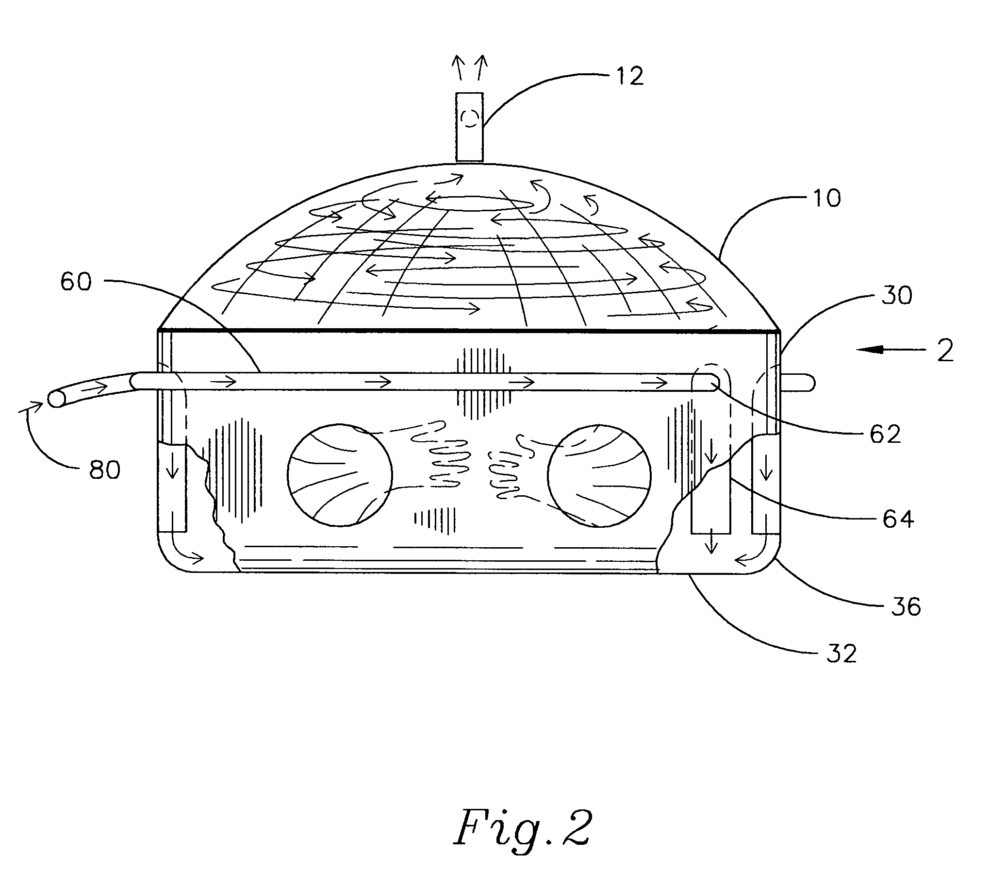
[0015]The present invention is a rigid-bodied welding chamber 2 (FIG. 1), comprising a transparent dome 10 that covers a rigid enclosure 30. FIG. 1 illustrates the chamber 2 in an open position, while FIGS. 2 and 3 illustrate the chamber in an air-tight closed position. Preferably the dome 10 is constructed of a high-strength acrylic, polycarbonate or other suitable strong yet substantially transparent material. The enclosure 30 is preferably made from a rigid sheet metal or other strong, durable material. A pair of hinges 22 is used to pivotably mount the dome 10 to the enclosure 30 at one edge of thereof

[0016]A resilient gasket 20 (FIGS. 1 and 2) provides an air-tight seal between the enclosure 30 and the dome 10 when the dome 10 is in the closed position. The gasket 20 is preferably attached to an edge of the dome 10 and is thereby lifted up and out of the way when the dome 10 is in its open position. While the gasket 20 can also easily be attached around an open edge of the encl...


PUM

PropertyMeasurementUnit
transparentaaaaaaaaaa
volumeaaaaaaaaaa
shapeaaaaaaaaaa

Abstract

A welding chamber having a laminar-vortex inert gas flow is disclosed. The welding chamber comprises a transparent dome that covers an open top side of a rigid generally rectanguloid enclosure. The dome includes a one-way vent for discharging ambient air from within the chamber while preventing the introduction of ambient air into the chamber. The enclosure includes a bottom and side walls that are joined at smooth, curved edges, and at least one side wall of the enclosure includes portholes with gloves for manually accessing the interior of the chamber while the dome is in a closed position. At least one gas distribution tube, a plurality of gas inlets and laminar-flow tunnels are included. In use, an inert gas is introduced into the distribution tube that substantially encircles the top of the enclosure. The inert gas is directed downward through the laminar flow tunnels, attached to the side walls of the enclosure, where the gas exits each tunnel with a laminar flow and is directed by the radiused bottom corners of the enclosure from a vertical flow to a horizontal flow across the bottom of the enclosure. As such, the inert gas creates a slow-moving counter-clockwise vortex pattern. In this manner, heavier-than-air argon gas fills the enclosure, displacing ambient air within the chamber, which is forced to rise and exit the chamber through a check valve vent in the top of the dome.

Description

FIELD OF THE INVENTION[0001]This invention relates to inert-gas-filled chambers, specially to chambers used to weld titanium and other refractory materials.BACKGROUND OF INVENTION[0002]Many exotic metals, such as titanium, cannot be welded in the presence of air without producing a weak and discolored weld. An inert gas such as argon or helium may be used to displace the air surrounding the weld, thereby solving the problem. A popular solution is to place the workpieces to be welded into a welding chamber that has been designed to purge the air and replace it with inert gas.[0003]There are currently on the market several types of welding chambers suitable for welding exotic metals in an inert-gas atmosphere. Each provides access to workpieces and a welding torch with plastic gloves through portholes in the side of the chamber. Each has a system for introducing the inert gas to the interior of the chamber. Each provides a vent in the chamber to expel air.[0004]A “beach-ball” type of ...

Claims


Application Information

Patent Timeline
Patent Type & Authority Patents(United States)
IPC IPC(8): B23K9/32
CPCB23K20/233B23K2203/14B23K2103/14
Inventor CORNE, JOSEPH E.
Owner CORNE JOSEPH E
Why Eureka
Try Eureka