Frequency modulation apparatus and frequency modulation method

a frequency modulation apparatus and frequency modulation technology, applied in the direction of instruments, furniture parts, electrographic processes, etc., can solve the problems of image distortion, misregistration and uneven coloring, and inability to accurately reproduce images, etc., to achieve high accuracy, superior printing quality, and printing ratio

Inactive Publication Date: 2006-10-31
CANON KK
View PDF11 Cites 14 Cited by
  • Summary
  • Abstract
  • Description
  • Claims
  • Application Information

AI Technical Summary

Benefits of technology

[0018]It is one object of the present invention to provide a frequency modulation apparatus that can correct, with high accuracy, a printing ratio and that can obtain a superior printing quality.

Problems solved by technology

Accordingly, the dot formation location for a latent image formed on a photosensitive member is slightly changed, and as a result, image distortion, misregistration and uneven coloring occur.
As a result, an image is printed while the magnification rate differs, depending on the portions of the image, and an accurate image reproduction is not possible.
However, as is apparent from FIGS. 10 and 11, the characteristic of the f-θ lens is complicated, and the distortion rate is increased, depending on the lens material.
Therefore, according to the method used for uniquely changing the frequency for one scan interval, and the method for dividing one scan interval and modulating the frequency in an analog manner, accuracy can not be expected for the correction of the print position shift that occurs due to the characteristic of the f-θ lens.
As a result, the printing quality is deteriorated.
As a result, misregistration in image forming occurs, and the image quality is remarkably deteriorated.
However, as is shown in FIG. 15, even for the same lens, the f-θ characteristic differs for each apparatus due to errors in the size and attachment of the lens, and irradiation location shifts can not be avoided.
Expensive lenses are required to reduce the variations in manufacturing lenses, and complicated operations are required to accurately position and attach the lenses.
And since for these calculations, complicated algorithms and procedures are required, and since all the setup values must be stored in FIG. 13, an increased memory (RAM) capacity is required.
Therefore, for a plurality of laser beams, it takes time to perform corrections such as the preparation of correction tables, and the operation is very demanding.

Method used


Image

  • Frequency modulation apparatus and frequency modulation method
  • Frequency modulation apparatus and frequency modulation method
  • Frequency modulation apparatus and frequency modulation method

Examples


first embodiment

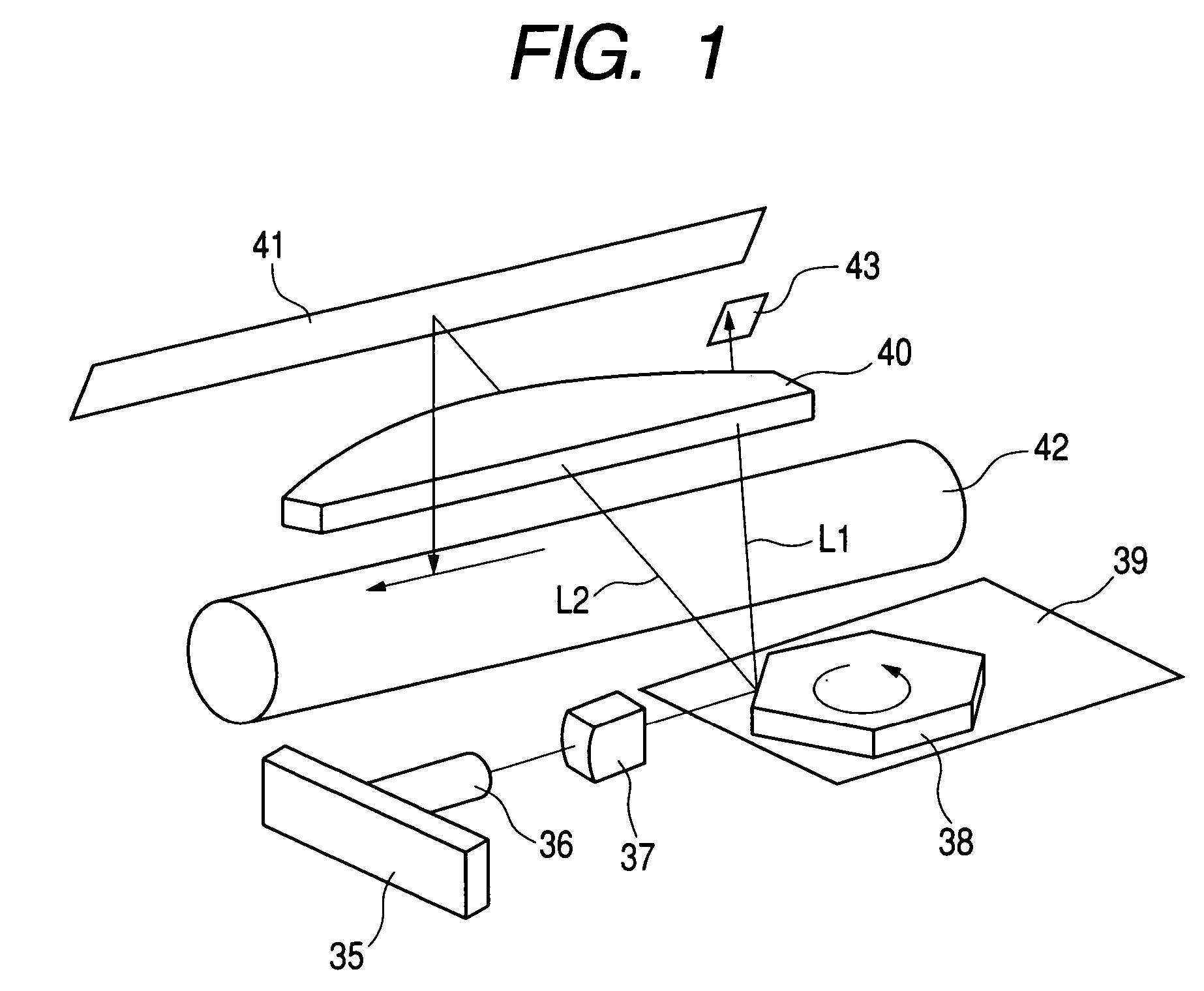
[0054]FIG. 1 is a specific diagram showing the configuration of the optical scanning unit of an image forming apparatus according to the present invention.

[0055]As is shown in FIG. 1, the optical scanning unit comprises: a laser unit 36 constituted by a semiconductor laser and a collimator lens (not shown), and a laser driving circuit 35 for driving the laser unit 36. As control signals for turning on or off a laser beam, a printing pattern signal and an image clock, which will be described later, are transmitted by a main scan magnification correcting circuit to the laser driving circuit 35.

[0056]In a non-image area, a laser beam L1 emitted by the laser unit 36 is passed through a cylindrical lens 37 and reaches a polygon mirror 38 that is rotated at a uniform angular velocity by a scanner motor unit 39. The laser beam L1 that has reached the polygon mirror 38 is deflected by the polygon mirror 38, and the deflected beam then enters an f-θ lens 40. Because of the condensing functio...

second embodiment

[0109]A second embodiment for performing re-correction will now be described while referring to FIG. 16. Actually, a block is formed of 100 or more segments. However, to simplify the explanation, one block is formed of twelve segments. The twelve segments are divided every four segments to form groups, and print patterns L1r, L2r and L3r are printed on paper and read by a scanner. Based on the obtained image data, the positions of the print patterns are detected while referring to the reference position (main scan start position), and shift distances h1, h2 and h3 from ideal values L1, L2 and L3 are obtained. Further, a shift distance (or shift amount) hn−n (n−1) for each block is calculated. In the example in FIG. 16, the following distances are obtained.

[0110]shift distance in block 1=h1

[0111]shift distance in block 2=h2−h1

[0112]shift distance in block 3=h3−h2

[0113]By using the shift distance (or shift amount) for each block and the image clock modulation method described above, m...

fourth embodiment

[0130]FIG. 18 is a specific diagram showing the arrangement of a multi-beam optical scan unit according to a In the following explanation, two beams are employed.

[0131]As is shown in FIG. 18, the optical scan unit includes a laser driving circuit 35 and a laser unit 36 driven by the laser driving circuit 35. The laser unit 36 is constituted by a semiconductor laser (not shown) that can emit two laser beams at the same time and a collimator lens (also not shown). The laser driving circuit 35 receives an image signal and an image clock that will be described later, and drives the semiconductor laser based on the image signal and the image clock.

[0132]In a non-image area, two laser beams L1 emitted by a laser unit 36 pass through a cylindrical lens 37 and reach a polygon mirror 38 that is rotated at a uniform angular velocity by a scanner motor unit 39. The laser beams that reach the polygon mirror 38 are deflected by the polygon mirror 38, and the deflected laser beams L1 then enter ...


PUM


Abstract

Disclosed are a frequency modulation apparatus and a frequency modulation method for generating an image clock that is used for turning on/off a laser beam that scans an image bearing member, such as a photosensitive drum. The frequency modulation apparatus divides, into a plurality of segments for each pixel, a main scan line on an image bearing member, and calculates auxiliary clock periods based on a reference clock period and variable-magnification coefficients corresponding to the segments. Then, the frequency modulation apparatus generates image clocks for the respective segments based on an initial predesignated period value and the obtained auxiliary clock periods. Furthermore, the frequency modulation apparatus includes a detecting device for detecting a difference between a reference value stored in a memory and an actual laser irradiation location, and corrects a shift in the laser irradiation location in accordance with the detection results obtained by the detecting device.

Description

BACKGROUND OF THE INVENTION[0001]1. Field of the Invention[0002]The present invention relates to a frequency modulation apparatus and a frequency modulation method for generating an image clock that is used for turning on / off a laser beam that scans an image bearing member, such as a photosensitive drum.[0003]2. Related Background Art[0004]In an electrophotographic image forming apparatus, generally, latent image forming is performed by turning on or off a laser beam emitted by a semiconductor laser and by exposing a photosensitive drum to the laser beam using a polygon mirror, and the image forming is performed by developing the latent image to obtain a toner image and transferring the toner image to a recording medium.[0005]For this image forming apparatus, a constant clock is always employed as an image clock that is required for a laser controller that turns on or off a laser beam in accordance with input image data, and as a reference clock that is used as a reference for the g...

Claims


Application Information

Patent Timeline
Patent Type & Authority Patents(United States)
IPC IPC(8): B41J2/435G03G15/04H04N1/047
CPCH04N1/047A47B67/04A47B88/477A47B88/50E05B65/463
Inventor SEKI, YUICHIENDO, SATOSHINAKAGAWA, ATSUSHI
Owner CANON KK
Why Eureka
Try Eureka