Method and arrangement for low-distortion recording of intensity patterns occurring on a contact surface through frustrated total reflection

Active Publication Date: 2006-10-31
CROSS MATCH TECH
View PDF12 Cites 28 Cited by
  • Summary
  • Abstract
  • Description
  • Claims
  • Application Information

AI Technical Summary

Benefits of technology

[0017]It is the primary object of the invention to find a novel possibility for recording intensity patterns occurring on a support surface according to the principle of frustrated total reflection which achieves a high-resolution, low-distortion image of the intensity pattern using simple optical arrangements. A further object consists in achieving a reproducible accuracy in image recording such that it is also suitable for forensic purposes for identification of parts of skin.

Problems solved by technology

cylindrical lens systems, although these are not suitable for forensic applications due to insufficient possibilities for correction (see, e.g., Stoltzmann et al., “Versatile anamorphic electronic fingerprinting: Design and manufacturing considerations”, SPIE, vol.
Devices with additional correction prisms require a rigid arrangement of the prisms and imaging optics elements relative to one another, which is disadvantageous particularly when installing the device within a predetermined volume.
Further, the correction prisms are expensive to produce compared to round optics and have a relatively large mass which is disadvantageous for the total mass of the device.
In addition, the chromatic aberration occurring in the arrangement limits the optical performance of a system of this kind.
Devices with telecentric imaging optics generally have low light power and therefore require a stronger illumination, high-sensitivity sensors or a long time for image generation and are therefore susceptible to interference during image acquisition.
However, like the large field lenses needed for telecentric imaging, cylindrical lenses are too expensive for applications with large recording areas.
In general, cylindrical optics are difficult to produce (and therefore expensive) and, above all, can not be corrected sufficiently to enable their use for forensic purposes.
35, September 1996, 5242–5245, is also only suitable for use with small recording areas such as for recording individual fingerprints, since it is difficult to connect them to the prism without defects and they drive up the cost of the device.
Displacement optics and inclination optics (see, e.g., R. T. Hebert, op.cit.) which are shaped into wave-guiding multi-element structures require the production of complex optical surfaces which are difficult to produce and are therefore expensive.
In this case also, large-diameter lenses are required in order to achieve an acceptable light intensity of the system, and it is not possible to eliminate distortion completely.

Method used


Image

  • Method and arrangement for low-distortion recording of intensity patterns occurring on a contact surface through frustrated total reflection
  • Method and arrangement for low-distortion recording of intensity patterns occurring on a contact surface through frustrated total reflection
  • Method and arrangement for low-distortion recording of intensity patterns occurring on a contact surface through frustrated total reflection

Examples


Embodiment Construction

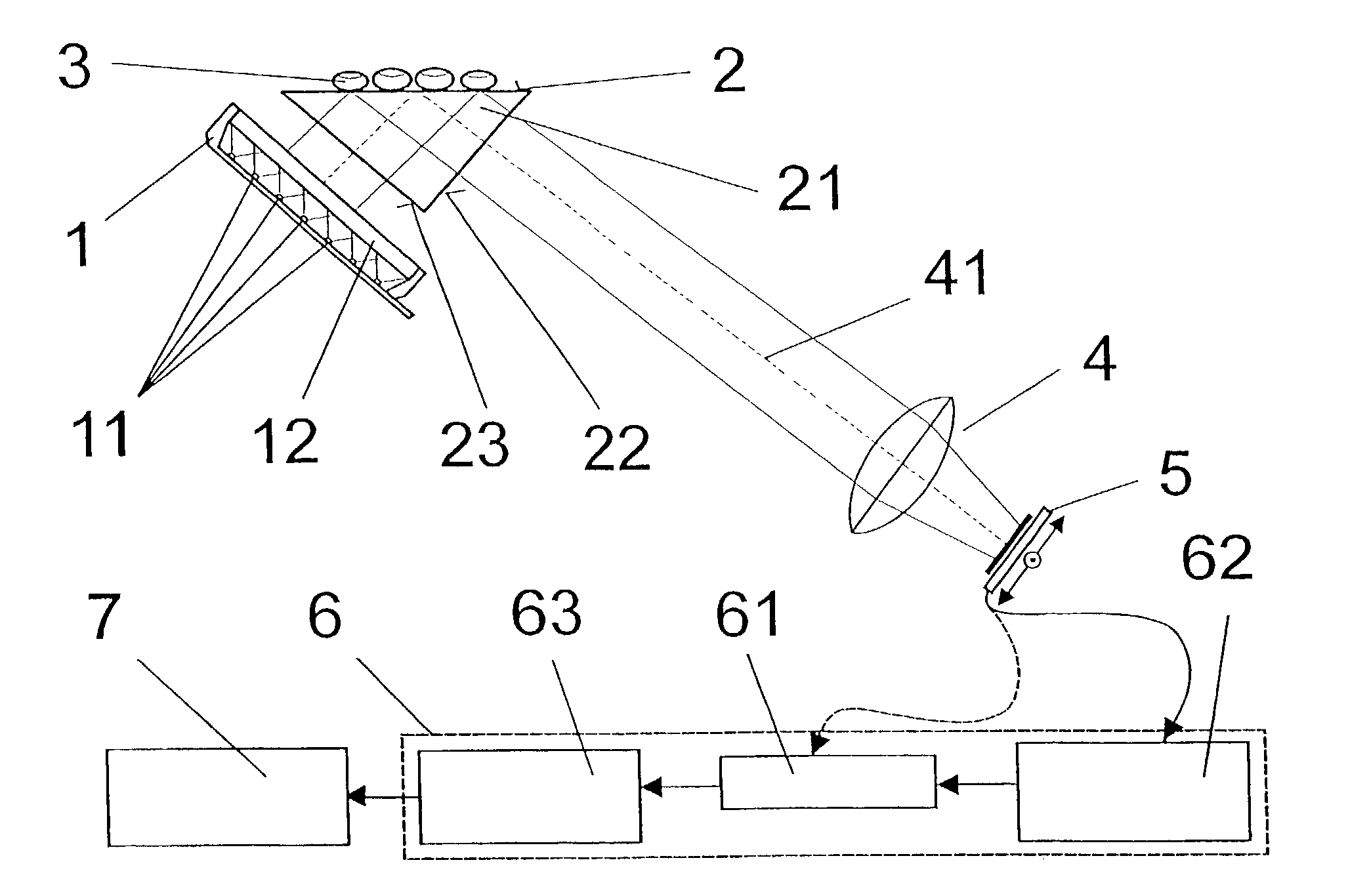
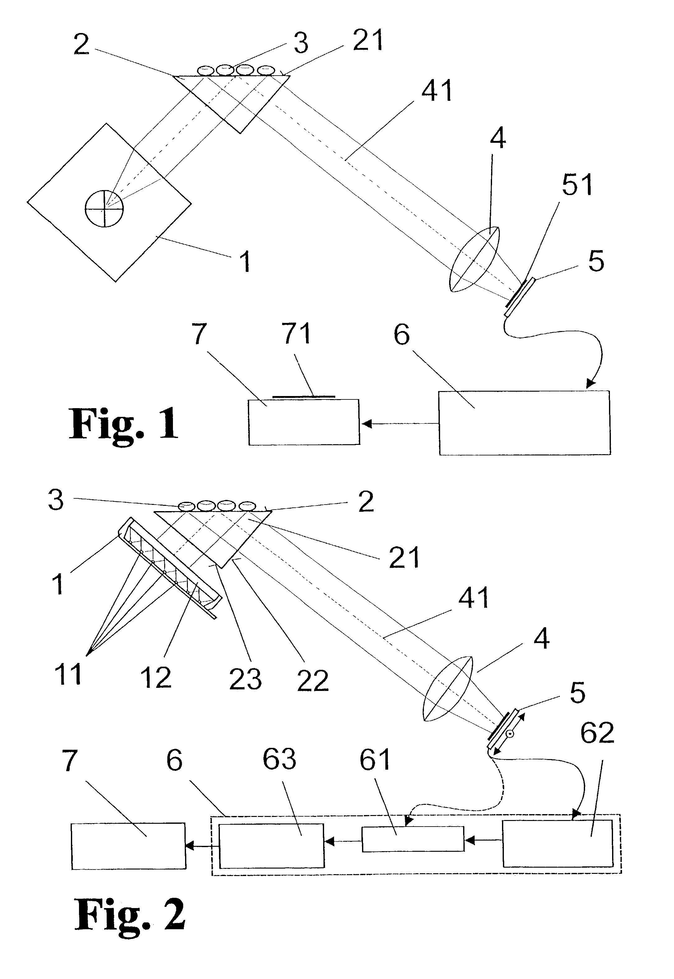
[0054]As is shown in FIG. 1, the basic construction of the arrangement according to the invention comprises a light source 1, a prism 2 with a support surface 21 with which a measurement object 3 (e.g., the fingers of a hand or other parts of human skin) is brought into contact, an optically imaging system, preferably a commonly available objective 4, and an image sensor 5. The objective 4 generates a sharp image of the support surface 21 on the image sensor 5 at an angle of the total reflection of the light coming from the light source 1. The image sensor 5 is followed by a rectification device 6 and an output unit 7.

[0055]FIG. 2 shows a more specialized construction than that shown in FIG. 1. The rectification device 6 contains at least one image storage 61, an electronic rectification unit 62 being arranged in front of the latter, and a mathematical rectification unit 63. The electronic rectification unit 62 is closely linked with a scanning and readout unit 52 (which possibly al...


PUM


Abstract

A method and an arrangement for recording intensity patterns occurring on a contact surface by frustrated total reflection, particularly for low-distortion recording of relatively large-area fingerprints, handprints or footprints or other parts of the skin. It is an object of the invention to find a novel possibility for recording intensity patterns occurring on a support surface according to the principle of frustrated total reflection which achieves a high-resolution, low-distortion image of the intensity pattern using simple optical arrangements. This object is met, according to the invention, in that a support surface for the measurement object is illuminated homogeneously by a light source at an angle of total reflection, an image of the support surface is imaged on the image sensor as an intensity pattern only by of an imaging optical system, so that the image is imaged on the image sensor so as to be distorted but sharp in all parts of the image, and light from the light source which is totally reflected at the support surface enters parallel to the axis of the optical system, the image of the support surface is scanned by the image sensor with substantially more image elements (pixels) than those required for the desired resolution in the output-side final image of the intensity pattern, and the optoelectronically converted, trapezoidally distorted image is rectified by displacement, interpolation and averaging operations based on the generation of combined pixel data from a data surplus occurring as a result of the increased quantity of recorded pixels compared to the necessary quantity of pixels in the final image.

Description

CROSS-REFERENCE TO RELATED APPLICATION[0001]This application claims priority of German Application No. 101 63 351.3, filed Dec. 14, 2001, the complete disclosure of which is hereby incorporated by reference.BACKGROUND OF THE INVENTION[0002]a) Field of the Invention[0003]The invention is directed to a method and an arrangement for recording intensity patterns occurring on a contact surface by means of frustrated total reflection, particularly for low-distortion recording of relatively large-area fingerprints, handprints or footprints or other parts of the skin.[0004]b) Description of the Related Art[0005]In known devices for taking fingerprint images and handprint images which work by total internal reflection (TIR) on prisms, a perspective imaging of the contact surface or support surface in which the image of the impression is distorted trapezoidally and highly compressed in one direction requires correction in order to achieve the same resolution and the same imaging scale at all ...

Claims


Application Information

Patent Timeline
IPC IPC(8): G06K9/00G02B27/18G06T1/00G06T3/00
CPCG06K9/00067G06V40/1347
Inventor HILLMANN, JUERGEN
Owner CROSS MATCH TECH
Why Eureka
Try Eureka