Low noise converter employed in satellite broadcast reception system and receiver apparatus

a receiver apparatus and low noise technology, applied in the field of low noise converters, can solve the problems of increasing cost, increasing cost, complex structure, etc., and achieve the effects of low cost, low noise and high performance property

Inactive Publication Date: 2006-10-31
SHARP KK
View PDF3 Cites 8 Cited by
  • Summary
  • Abstract
  • Description
  • Claims
  • Application Information

AI Technical Summary

Benefits of technology

[0013]In view of the foregoing, a main object of the present invention is to provide a low noise converter of low cost and of high performance property, less susceptible to a spurious harmonic component.

Problems solved by technology

However, this approach will render the structure complex and increase the cost.
Such requirements will increase the cost.
Thus, the cost will be increased.

Method used


Image

  • Low noise converter employed in satellite broadcast reception system and receiver apparatus
  • Low noise converter employed in satellite broadcast reception system and receiver apparatus
  • Low noise converter employed in satellite broadcast reception system and receiver apparatus

Examples


Embodiment Construction

[0044]Embodiments of the present invention will be described in detail hereinafter with reference to the drawings. In the drawings, the same or corresponding components have the same reference characters allotted, and description thereof will not be repeated.

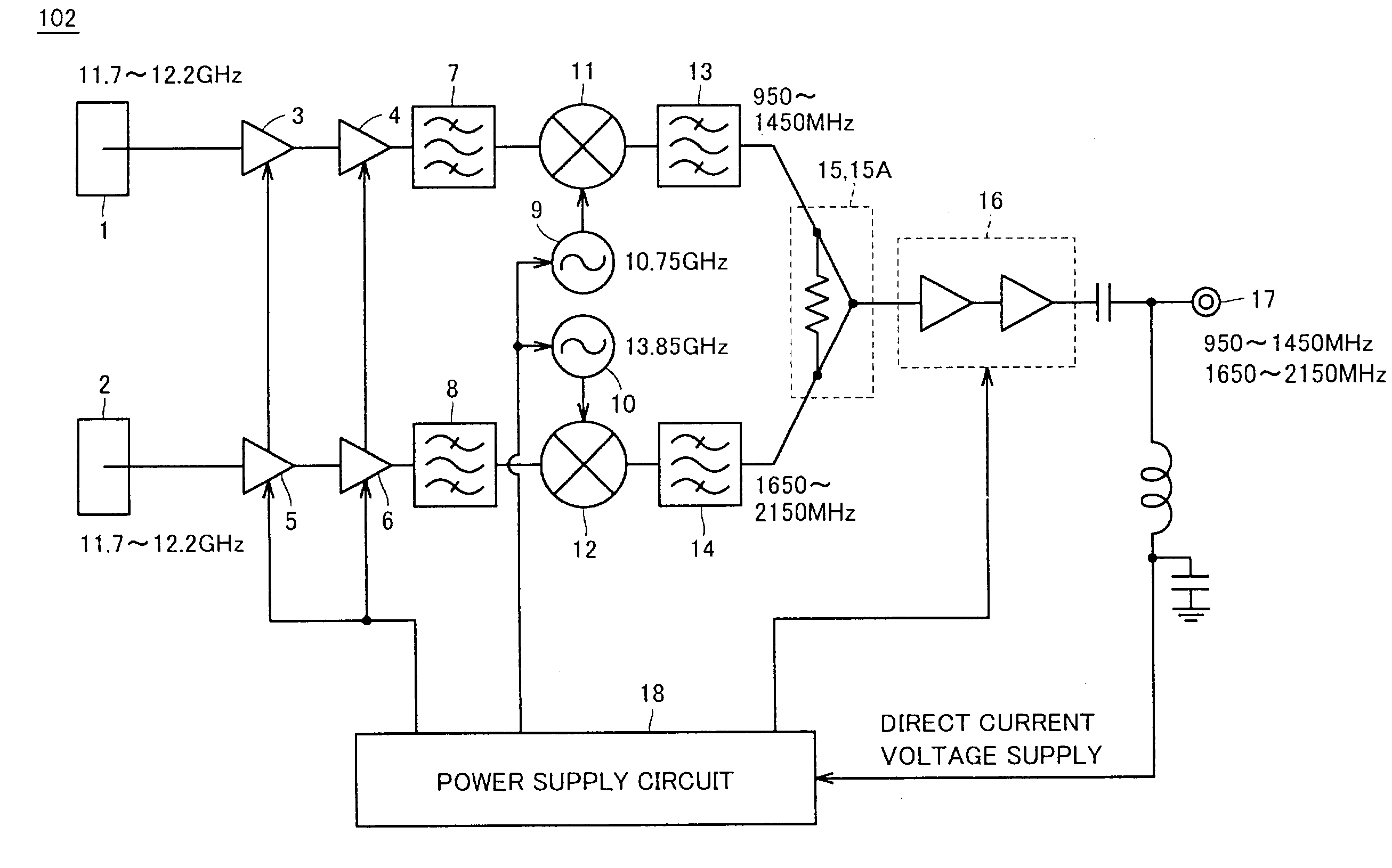
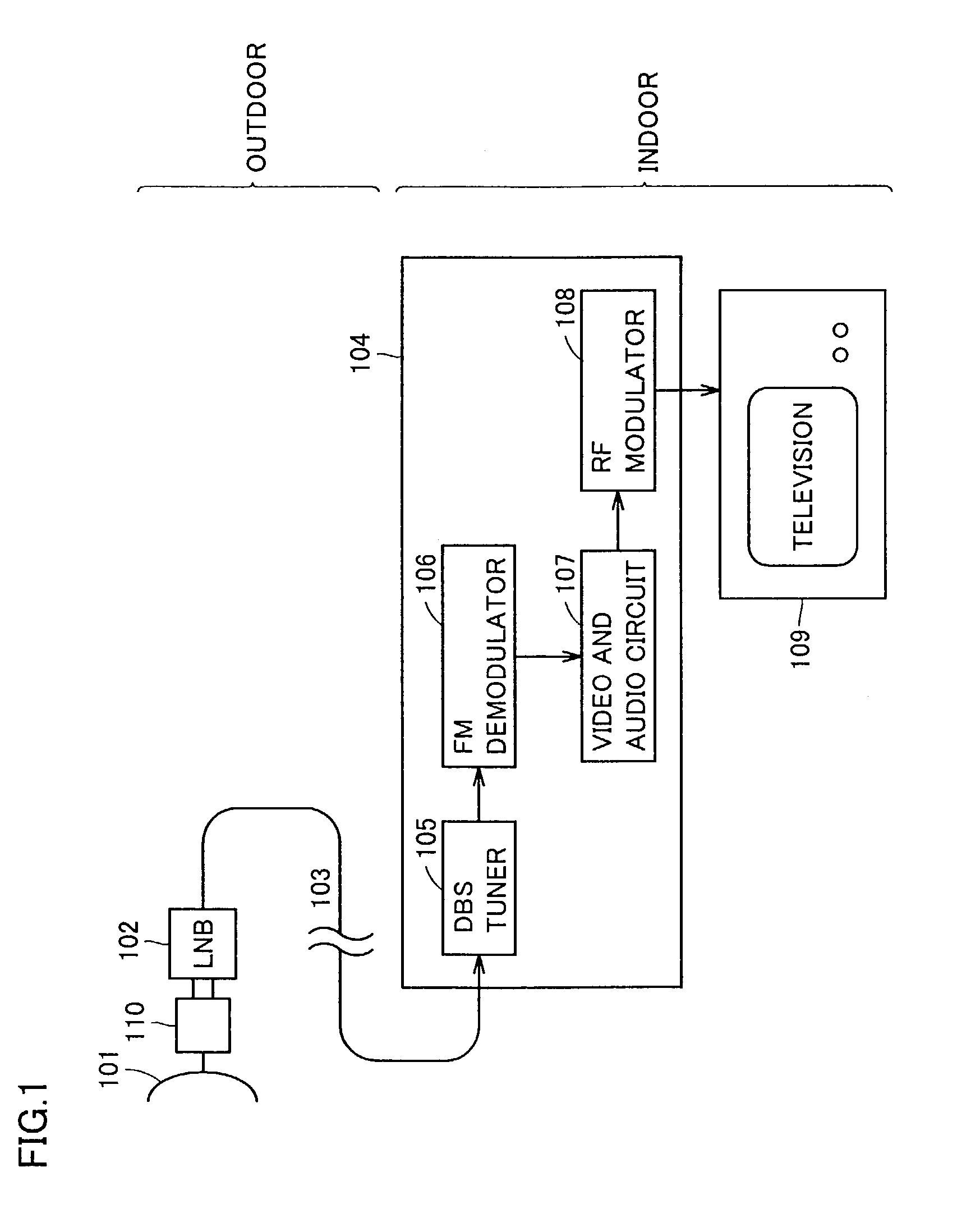
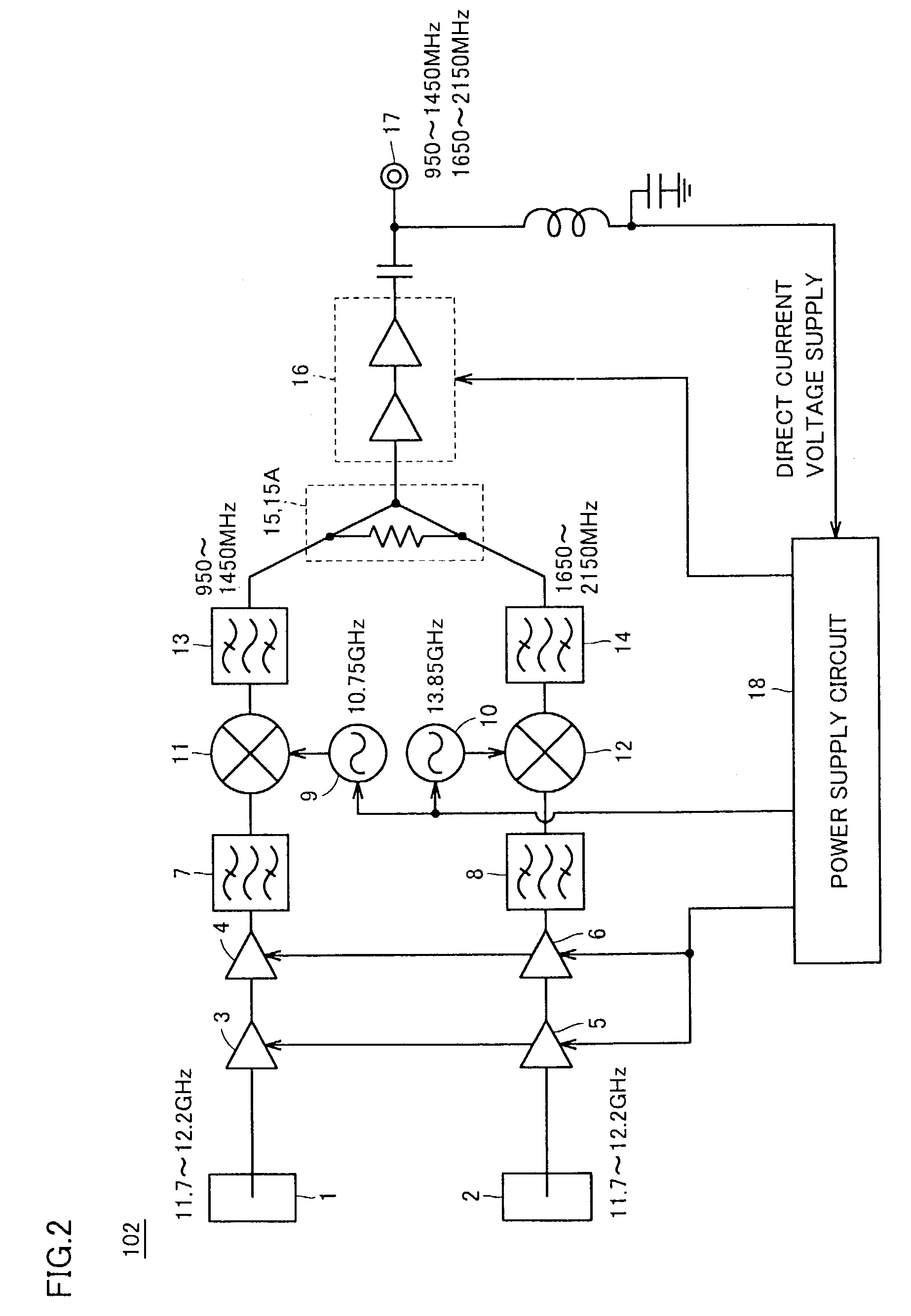
[0045]FIG. 1 is a schematic block diagram of an entire structure of a satellite broadcast reception system in which an LNB of the present invention is employed. Referring to FIG. 1, an antenna 101 is attached with a feed horn and a cross polarization separator 110 at a succeeding stage. An LNB 102 is a portion of an element called “outdoor” of the present system, and is attached at a succeeding stage of cross polarization separator 110. LNB 102 amplifies a weak wave from a satellite with low noise to supply a signal of low noise and sufficient level to a connected indoor receiver 104 via a coaxial cable 103.

[0046]Indoor receiver 104 includes a DBS tuner 105, an FM demodulator 106, a video and audio circuit 107, and an RF modulat...


PUM


Abstract

A reception frequency band is selected at 11.7 GHz–12.2 GHz, the local oscillating frequencies of local oscillators are determined at 10.75 GHz and 13.85 GHz, respectively, and each intermediate frequency band is selected at 950 MHz–1450 MHz and 1650 MHz–2150 MHz, respectively, so that the harmonic component of the frequency difference between local oscillation signals output from each local oscillator is not present in the frequency band of each intermediate frequency signal output from each mixer and in the reception band of polarization signals applied to input terminals.

Description

BACKGROUND OF THE INVENTION[0001]1. Field of the Invention[0002]The present invention relates to low noise converters, particularly a low noise converter employed as an LNB (Low Noise Block down-converter) incorporated in a receiver of an antenna for satellite signal transmission / reception, converting two input signals differing in polarization into signals of different intermediate frequencies (IF) for transmission to an indoor unit (indoor receiver), and a receiver apparatus including such a low noise converter.[0003]2. Description of the Background Art[0004]FIG. 14 is a block diagram showing a first conventional LNB. The LNB of FIG. 14 is directed to satellite broadcasting / communication reception that allows reception of a plurality of polarized waves, employed for receiving the Ku band satellite signals of the United States.[0005]According to FIG. 14, a reception signal of input frequency 11.7 GHz–12.2 GHz is divided into a horizontal polarization signal and a vertical polarizat...

Claims


Application Information

Patent Timeline
Patent Type & Authority Patents(United States)
IPC IPC(8): H04H1/00H01P5/19H01P7/10H03B5/18H03D7/12H03D9/06H04B1/18H04B1/26H04N5/44
CPCH01P5/16H01P7/10H03B5/187H03D7/125H03D9/0675H04H40/90
Inventor NAKAMURA, MAKIO
Owner SHARP KK
Why Eureka
Try Eureka