Pathcorrection for an industrial robot

a robot and path correction technology, applied in the field of industrial robots, can solve the problems of large number of error sources of industrial robots, difficult control of motors, and high accuracy requirements, and achieve the effects of accurate measurement of reference points, increased accuracy of robot movements, and improved accuracy

Inactive Publication Date: 2006-10-31
ABB (SCHWEIZ) AG
View PDF16 Cites 73 Cited by
  • Summary
  • Abstract
  • Description
  • Claims
  • Application Information

AI Technical Summary

Benefits of technology

[0029]From a second aspect of the invention, the accuracy of the movements of the robot is increased by means of a method which includes the methods described above. In a first part method, an adjustment of the parameters controlling the drive devices is iterated according to the first method. In a second iteration, the result from a first iteration is introduced, the result of which is brought to influence the control system in a third it ration, etc. In a second part method, the outcome path is first iterated with respect to orientation, position and finally shape. In a second iteration, the results obtained from the first iteration are brought to influence the control system, etc. Finally, in order to obtain a higher accuracy, the first meth

Problems solved by technology

However, an industrial robot has a large number of error sources, which in normal cases do not permit the requirements for accuracy, which are made by such processes, to be achieved.
The error may be due to inaccuracy and play in gears, faults in the geometry of articulated rods, for example when using parallel links for transmission of torques to axis 3, etc.3. Measuring system errors, which, for example, are due to the fact that the angle-reference value corresponding to the axis angle zero is incorrect or that the noise level of the sensor signal is too high.4. Downward deflection errors, which are due to the fact that gears and arms are not fully rigid.
The situation is aggravated by the fact that, for example, gears may have a torque-dependent stiffness value.5. Calibration errors, which comprise the errors arising when the robot is being installed.
Examples of calibration errors are the position errors and orientation errors which arise when the orientation and operating point of the tool are to be measured relative to the mounting plate of the robot wrist and when the position and orientation of the robot foot are to be measured relative to the surroundings of the robot.6. Dynamic deflection errors, which arise when the servo controls the motor positi

Method used


Image

  • Pathcorrection for an industrial robot
  • Pathcorrection for an industrial robot
  • Pathcorrection for an industrial robot

Examples


Embodiment Construction

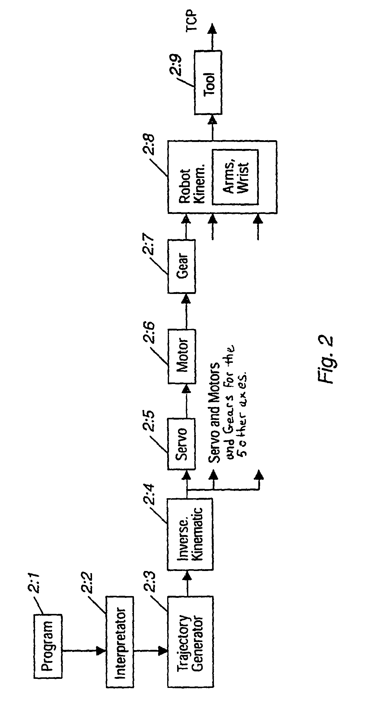
[0047]A method for compensation of dynamic broadband error sources according to the invention is shown in FIG. 3, which is an extension of FIG. 2. In FIG. 3 the blocks representing servos 2:5, motors 2:6 and gears 2:7 are shown for all the axes of a 6-axis robot. In the case where the invention is used for other types of manipulators, for example position adjusters having two or three axes, the invention is used for a smaller number of axes, or in the case of coordinated running between the robot and an external manipulator, the invention is used for the axes of both the robot and the manipulator at the same time. From each servo, an arrow extends to the corresponding motor representing the motor torque controlled by the servo, and from each motor a feedback extends to the corresponding servo, representing the measured signal from the axis-angle measuring device of the motor. A module for direct-kinematics calculation 3:1 receives signals from the axis-angle measuring device of the ...


PUM

PropertyMeasurementUnit
Shapeaaaaaaaaaa

Abstract

A method for an industrial robot to increase accuracy in movements of the robot. A first path is formed by bringing a tool supported by the robot to adopt a plurality of generated positions. A plurality of observed positions of the tool moving along the first path are determined. A second path is formed of the determined tool positions. A correction is determined by a path deviation between geometrically determined positions in the first path and the second path.

Description

TECHNICAL FIELD[0001]The present invention relates to a method for an industrial robot. More particularly, the invention relates to a method for obtaining high-precision control of an industrial robot. The method comprises an iterative process, by means of which the absolute accuracy of the robot is tuned by automatic means. The invention also relates to a device and a computer program, by means of which the method is automatically carried out, as well as a computer-readable medium, on which the computer program is stored. By absolute accuracy is meant here that the operating point of the robot is to achieve the absolute position which is indicated in the drawing or a CAD model of the work object, that is, positions defined in the reference coordinate system of the work object.[0002]By an industrial robot is meant a manipulator and a control system. The manipulator normally comprises one to six axes but may also comprise external axes connected to such a manipulator, for example for...

Claims


Application Information

Patent Timeline
IPC IPC(8): G06F19/00B25J9/10B25J9/16B25J9/18
CPCB25J9/1638B25J9/1641B25J9/1692G05B2219/36415G05B2219/39024G05B2219/39033G05B2219/39056G05B2219/39176G05B2219/39181G05B2219/39191G05B2219/41084Y02P90/80
Inventor GUNNARSSON, SVANTENORRLOF, MIKAELHOVLAND, GEIRCARLSSON, ULFBROGARDH, TORGNYSVENSSON, TOMMYMOBERG, STIG
Owner ABB (SCHWEIZ) AG
Why Eureka
Try Eureka