Jig saw with laser alignment system

a laser alignment and jig saw technology, applied in the direction of power driven reciprocating saws, metal sawing accessories, lighting and heating apparatus, etc., can solve the problems of waste of time and material, and achieve the effect of more precise blade movemen

Inactive Publication Date: 2006-11-07
CHERVON INT TRADING
View PDF26 Cites 19 Cited by
  • Summary
  • Abstract
  • Description
  • Claims
  • Application Information

AI Technical Summary

Benefits of technology

[0003]In view of the foregoing disadvantages inherent in the prior art, it is an primary object of the present invention to provide an improved power saw, particularly a jig saw with a laser alignment system for projecting an optical alignment marker onto a workpiece for more precise movement of the blade during cutting.
[0008]Still yet another object of the present invention is to provide an improved jig saw with a laser alignment system that may be easily detached from the shield of the jig saw without the use of a tool in order to facilitate the replacement of battery cells.

Problems solved by technology

First, the operator is required to concentrate his observation exactly ahead of the cutting blade as the blade is pushed along the prescribed and prepared target line, it has to repeat this procedure several times in order to achieve proper alignment for precision, and this will result in waste of time and material.

Method used


Image

  • Jig saw with laser alignment system
  • Jig saw with laser alignment system
  • Jig saw with laser alignment system

Examples


Embodiment Construction

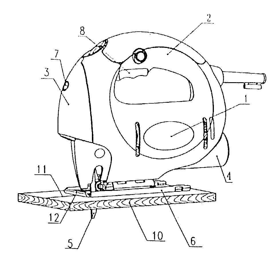
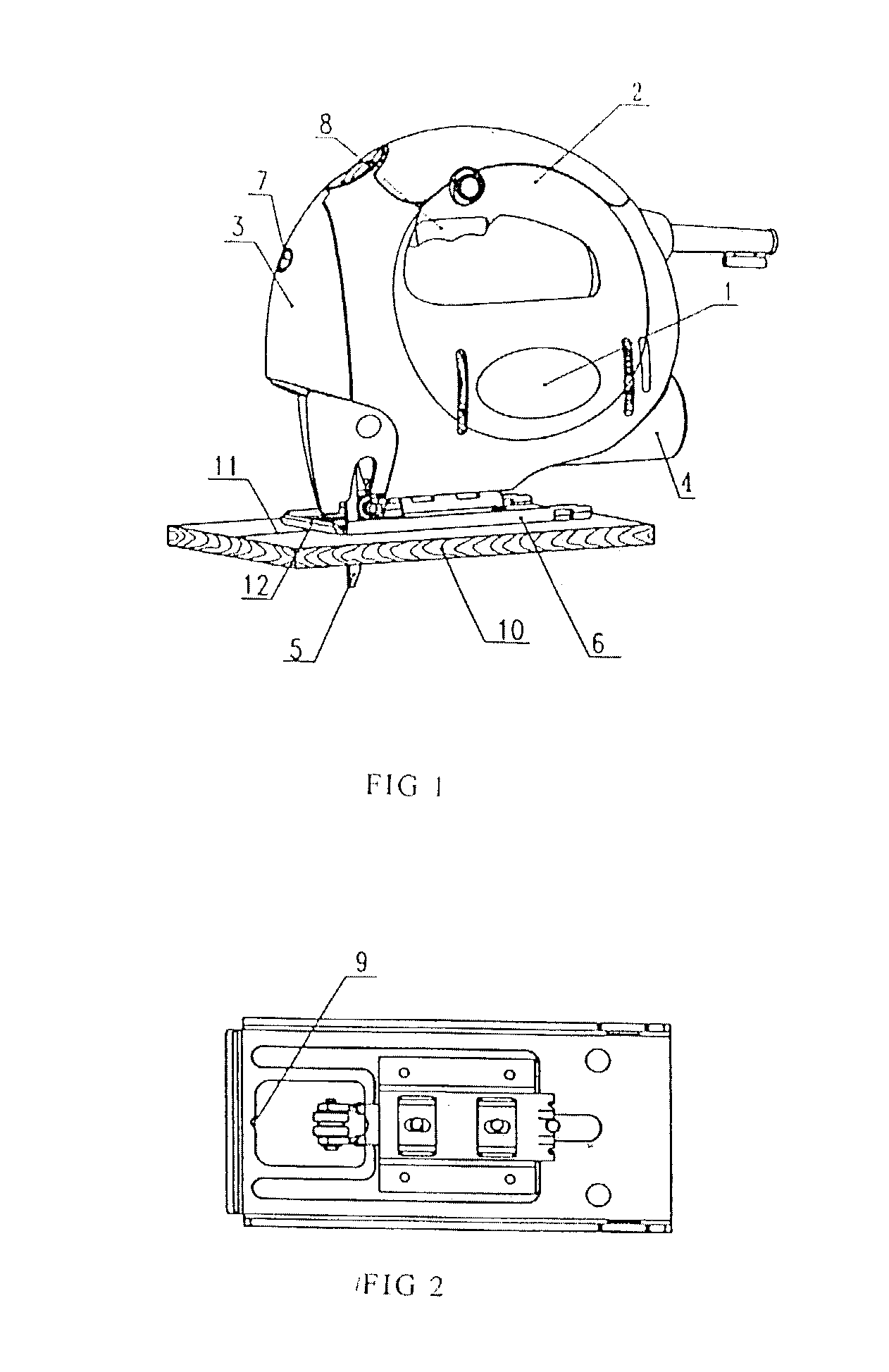
[0014]Referring to FIG. 1, the preferred embodiment of a new and improved jig saw with a laser alignment system comprises a body 1 with motor, a handle 2, a reciprocating saw blade 5, a base plate 6 with a lower planar surface adapted to ride on the work piece, the handle 2 also includes a main power switch trigger 8 coupled to the motor for stopping and starting the reciprocating of the saw blade 5, and a laser alignment system 3 provided on the front of the body 1, the jig saw also includes an adapter 4 for connecting a vacuum cleaner.

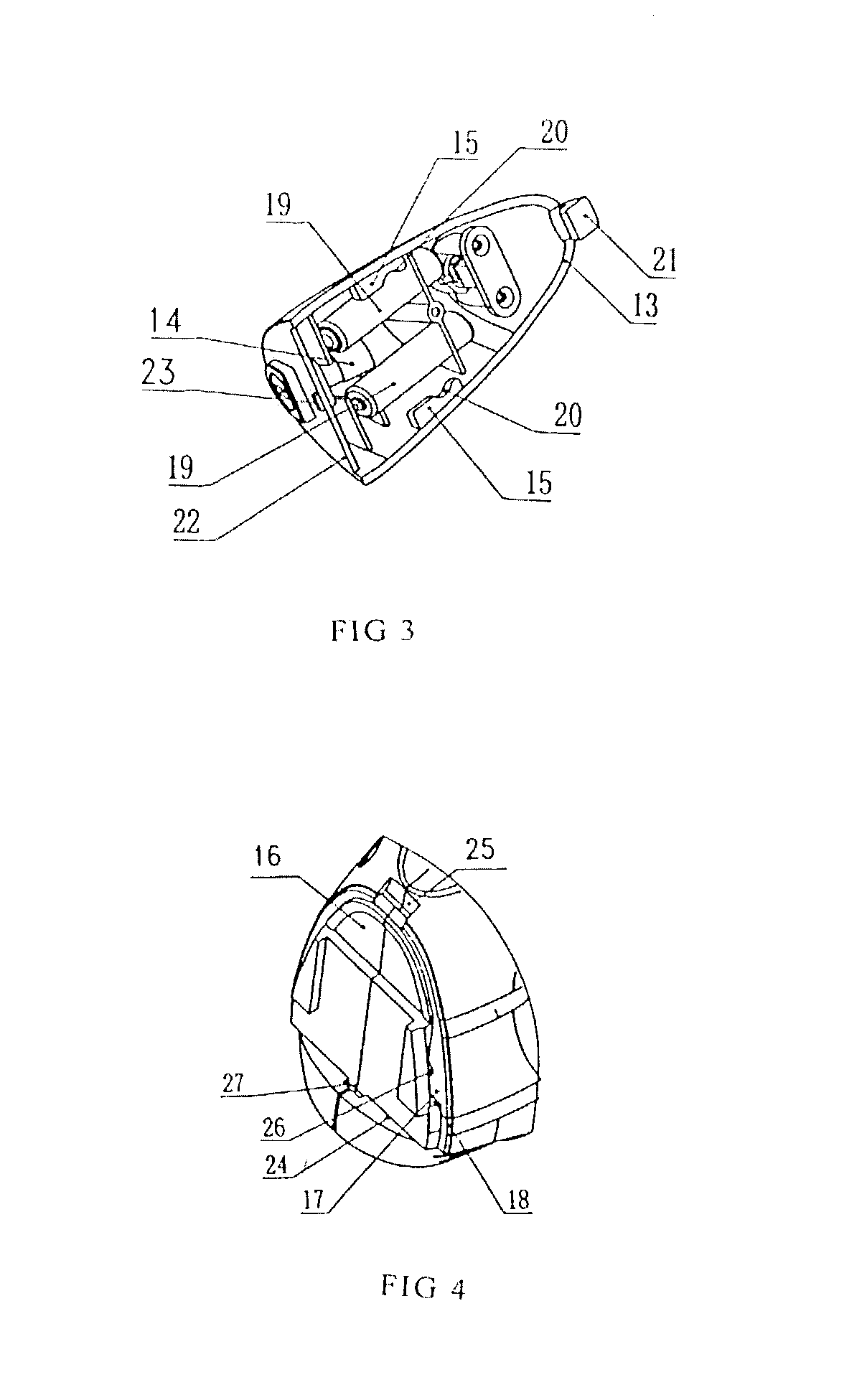
[0015]Referring to FIG. 1 and FIG. 3, the laser alignment system 3 comprises a laser generator 14, a switch 7 for turning on or turning off the laser generator 14. In this preferred embodiment, the laser alignment system 3 is positioned in front of the body 1. The laser generator 14 comprises a laser diode to project a point light, and some optical elements to convert point light to a planar segmented beam. The assembly ensures the projected laser be...


PUM

PropertyMeasurementUnit
movementaaaaaaaaaa
AC poweraaaaaaaaaa

Abstract

A jig saw for more precise movement during cutting with a laser alignment system for projecting a marker onto a workpiece to align with a target line to be cut. The laser alignment system comprises a housing, a laser generator within the housing, an internal battery supplying the laser generator, a switch which is positioned within the housing and independent of the main switch to turn on and turn off the laser generator. By turning on the switch, the laser generator projects a laser beam onto the workpiece ahead of the blade in alignment with the plane of the blade. The operator only needs to align the projected laser line along a target line on the workpiece to attain the more precise cutting without concentrating his observation exactly ahead of the cutting blade.

Description

FIELD OF THE INVENTION[0001]The present application relates to a power saw, and more particularly, to a jig saw with optical alignment system for projecting an optical alignment marker onto a workpiece.BACKGROUND OF THE INVENTION[0002]The prior electric saw, particularly a jig saw, is mainly used to cut wood, steel plate, plastic and so on by a motor to reciprocate a saw blade. In order to align the saw blade with a cutting line on a workpiece, the operator must typically bring the blade into contact with the workpiece to determine if the saw is properly aligned with the cutting line. As is familiar to those skilled in the art, such a jig saw has some disadvantages. First, the operator is required to concentrate his observation exactly ahead of the cutting blade as the blade is pushed along the prescribed and prepared target line, it has to repeat this procedure several times in order to achieve proper alignment for precision, and this will result in waste of time and material. Also...

Claims


Application Information

Patent Timeline
Patent Type & Authority Patents(United States)
IPC IPC(8): B27B19/02F21V33/00B23D59/00
CPCB23D59/003
Inventor WU, SHUMING
Owner CHERVON INT TRADING
Why Eureka
Try Eureka