Pipe bending apparatus and method

Active Publication Date: 2006-11-07
YAMAHA MOTOR CO LTD
View PDF5 Cites 3 Cited by
  • Summary
  • Abstract
  • Description
  • Claims
  • Application Information

AI Technical Summary

Benefits of technology

[0015]Another aspect of at least one of the inventions disclosed herein includes the realization that if a workpiece is disposed such that a liquid inlet end is disposed below a liquid outlet end while it is filled with

Problems solved by technology

Changes in cross-sectional area or shape of the exhaust pipe tend to disrupt the flow of exhaust gases and/or partially reflect pressure waves, which can reduce the power output of the engine, especially at high engine speeds.
However, when a tubular workpiece is bent, the outer side of the workpiece tends to collapse toward the inner side in

Method used


Image

  • Pipe bending apparatus and method
  • Pipe bending apparatus and method
  • Pipe bending apparatus and method

Examples


Embodiment Construction

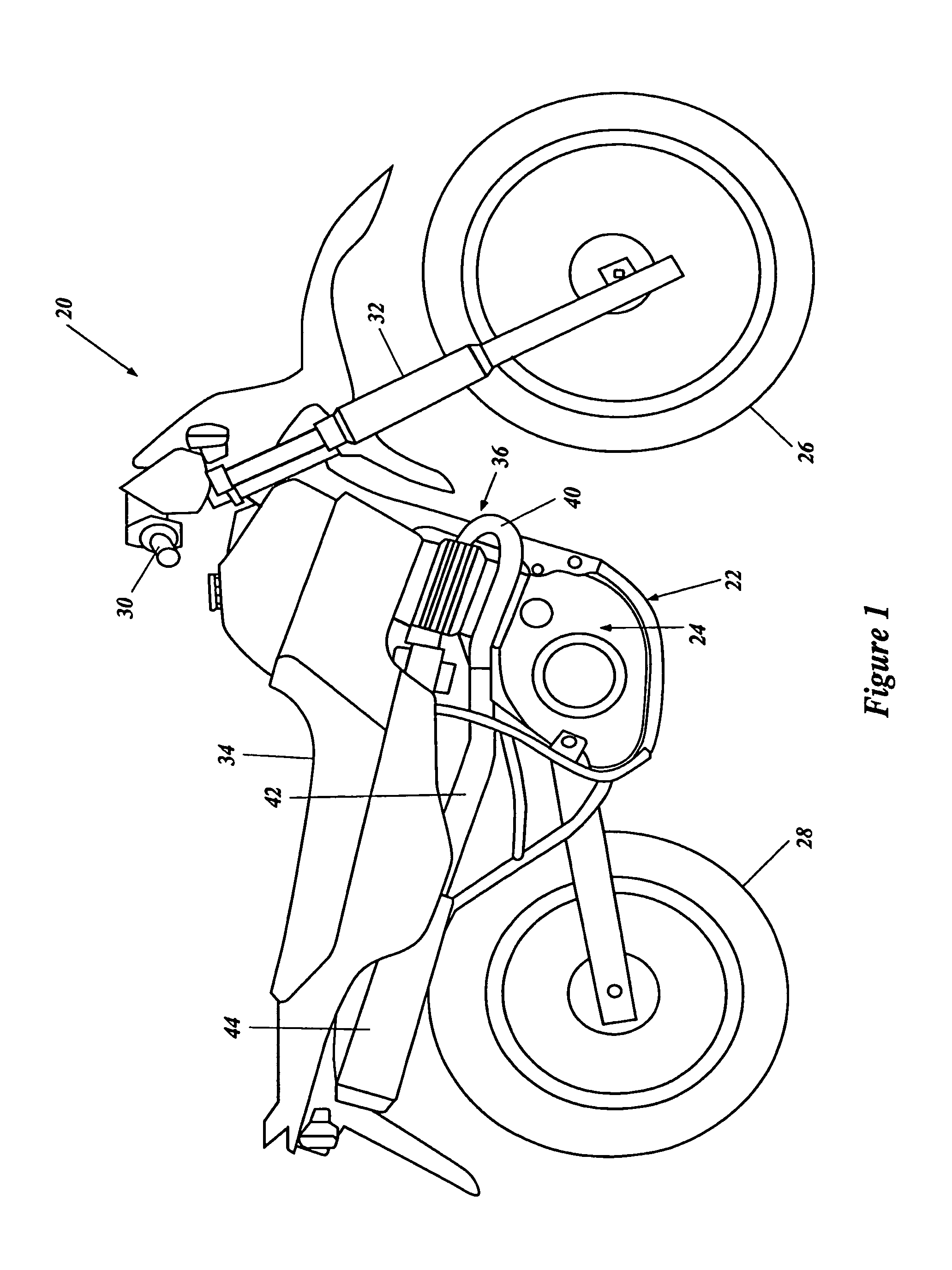
[0036]FIG. 1 illustrates a motorcycle 20 incorporating a preferred exhaust system. The motorcycle 20 is described in general detail in order to assist the reader's understanding of a preferred environment of use of the inventions disclosed herein.

[0037]The motorcycle 20 includes a frame 22, which supports an internal combustion engine 24 therein. Front and rear wheels 26, 28, respectively, are supported relative to the frame 22.

[0038]A handlebar assembly 30 is coupled to the front wheel 26 through a front fork assembly 32. The handlebar assembly 30 permits a rider of the motorcycle 20 to turn the front wheel 26 about a steering axis. The frame 22 also supports a seat assembly 34, which supports a rider of the motorcycle.

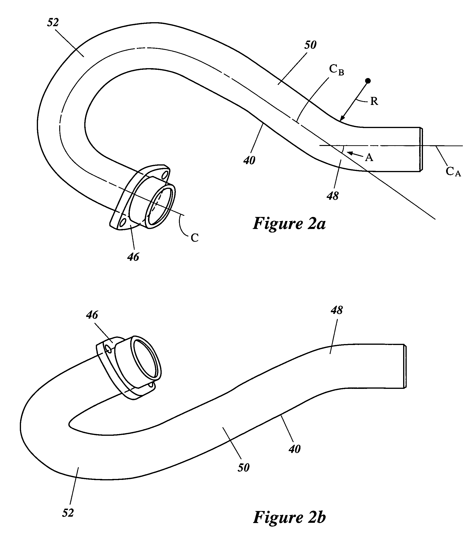
[0039]The engine 24 includes an exhaust system 36 to guide exhaust gases from a combustion chamber (not shown) of the engine 24 to the atmosphere. Preferably, the exhaust system 36 includes an exhaust pipe 40 extending from the engine 24 to a secondary exhaust pipe 4...


PUM

PropertyMeasurementUnit
Pressureaaaaaaaaaa
Angleaaaaaaaaaa
Bending strengthaaaaaaaaaa

Abstract

A pipe bending apparatus for performing a pipe bending method, wherein the method includes filling a workpiece with a liquid, pressurizing the liquid to a target pressure level, and bending the workpiece to create a bent pipe. Preferably, the pressure level is inversely proportional to the radius of the bend in the pipe. Furthermore, preferably the pressure is directly proportional to the bending angle of the pipe. Preferably, the pressure is maintained substantially at the target pressure during the bending process. Optionally, the pressure level can be increased during the bending process.

Description

RELATED APPLICATIONS[0001]The present application is based on Japanese Patent Application No. 2000-393172, filed Dec. 25, 2000, Japanese Patent Application No. 2001-137280, filed May 8, 2001, and Japanese Patent Application No. 2000-393229 filed Dec. 25, 2000, the contents of each of which is hereby expressly incorporated by reference.BACKGROUND OF THE INVENTION[0002]1. Field of the Invention[0003]The present application relates generally to an apparatus and method for bending a pipe and, more particularly, to an apparatus and method for introducing pressurized liquid into the interior of a pipe during bending to maintain the cross-sectional shape of the pipe.[0004]2. Description of the Related Art[0005]Vehicles powered by internal combustion engines, such as motorcycles, automobiles, snowmobiles, and all-terrain vehicles, for example, typically include an exhaust system to guide exhaust gases from one or more combustion chambers of the engine to the atmosphere. The exhaust system t...

Claims


Application Information

Patent Timeline
IPC IPC(8): B21D9/15B21D7/02B21D9/07
CPCB21D7/021B21D9/073B21D9/15
Inventor YOSHINO, TAMIOTASHIRO, YOJI
Owner YAMAHA MOTOR CO LTD
Why Eureka
Try Eureka