Production of fuels and lube oils from fischer-tropsch wax

a technology of lubricant oil and wax, which is applied in the direction of hydrocarbon oil cracking, hydrocarbon oil treatment products, organic chemistry, etc., can solve the problems of high conversion and concomitant, substantial loss of lubricant and higher boiling fuel, and high product yield. , to achieve the effect of low cloud and pour point and high product yield

Active Publication Date: 2006-11-07
EXXON RES & ENG CO
View PDF127 Cites 38 Cited by
  • Summary
  • Abstract
  • Description
  • Claims
  • Application Information

AI Technical Summary

Benefits of technology

[0004]By hydrodewaxing is meant the waxy feed and partially dewaxed lubricant oil fractions are contacted with hydrogen, and a hydrodewaxing catalyst that dewaxes mostly by isomerization as opposed to hydrocracking. This excludes dewaxing catalysts, such as ZSM-5, which dewax mostly by hydrocracking the waxy molecules, particularly the heavy lubricant fraction, to hydrocarbons boiling below the desired product range. A hydrodewaxing catalyst comprising a ZSM-48 zeolite (ZSM-48 zeolites herein include EU-2, EU-11 and ZBM-30 which are structurally equivalent to ZSM-48) component and a hydrogenation component, has been found to be particularly useful in the process of the invention. This process and catalyst combination have been found to produce dewaxed fuel and lubricant base stocks, including a heavy lubricant base stock, having acceptably low cloud and pour points, with relatively high product yield.

Problems solved by technology

However, these fuel and lubricant fractions have cloud and pour points too high to be useful as fuels and lubricant oils and must therefore be further processed (e.g., dewaxed), to acceptably low cloud and pour points.
This results in a substantial loss of lubricant and higher boiling fuel, with concomitant low product yield.
The problem of high conversion and concomitant low product yield is exacerbated, when dewaxing a waxy, heavy lubricant oil fraction to an acceptable cloud point.

Method used


Image

  • Production of fuels and lube oils from fischer-tropsch wax
  • Production of fuels and lube oils from fischer-tropsch wax

Examples


example

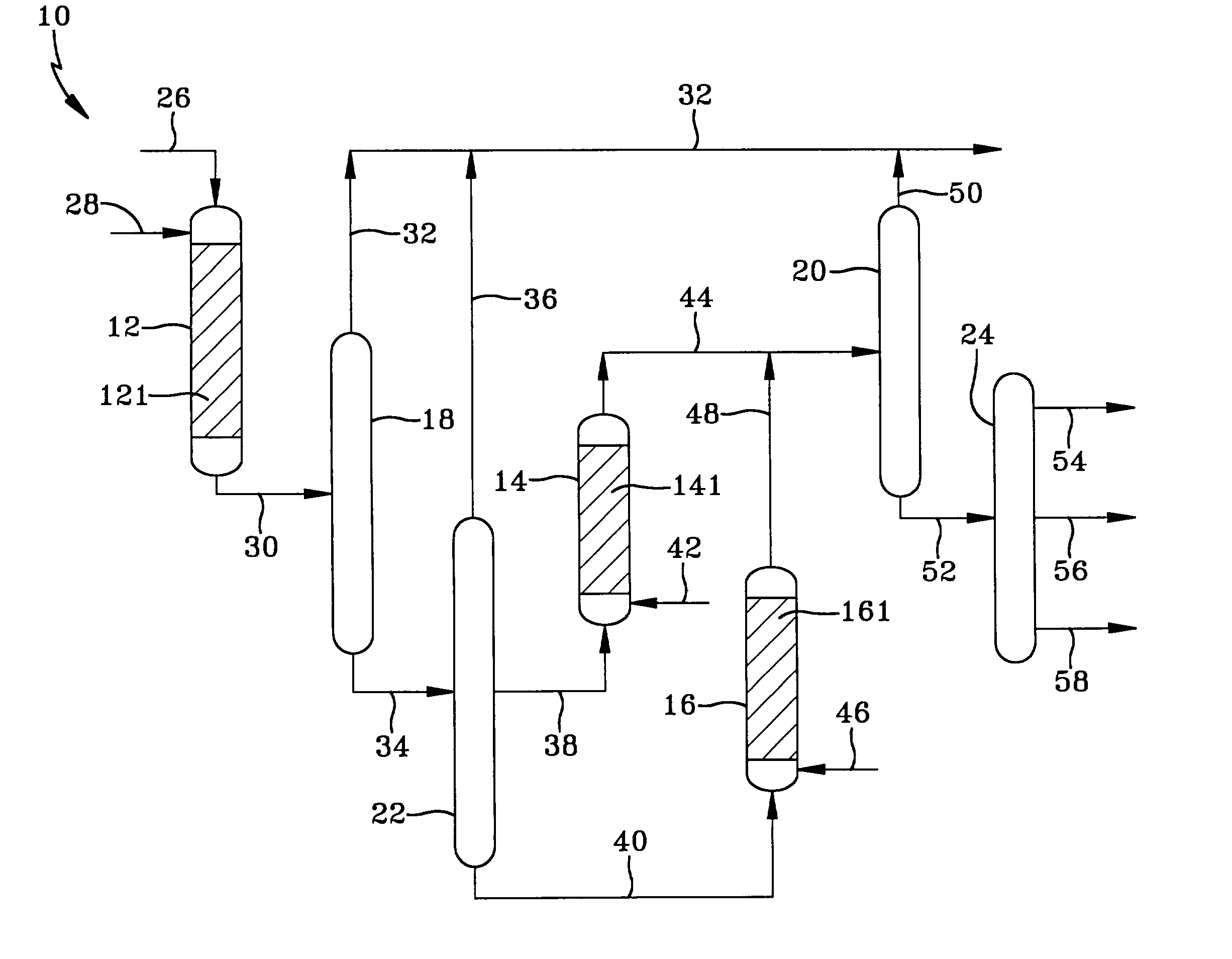
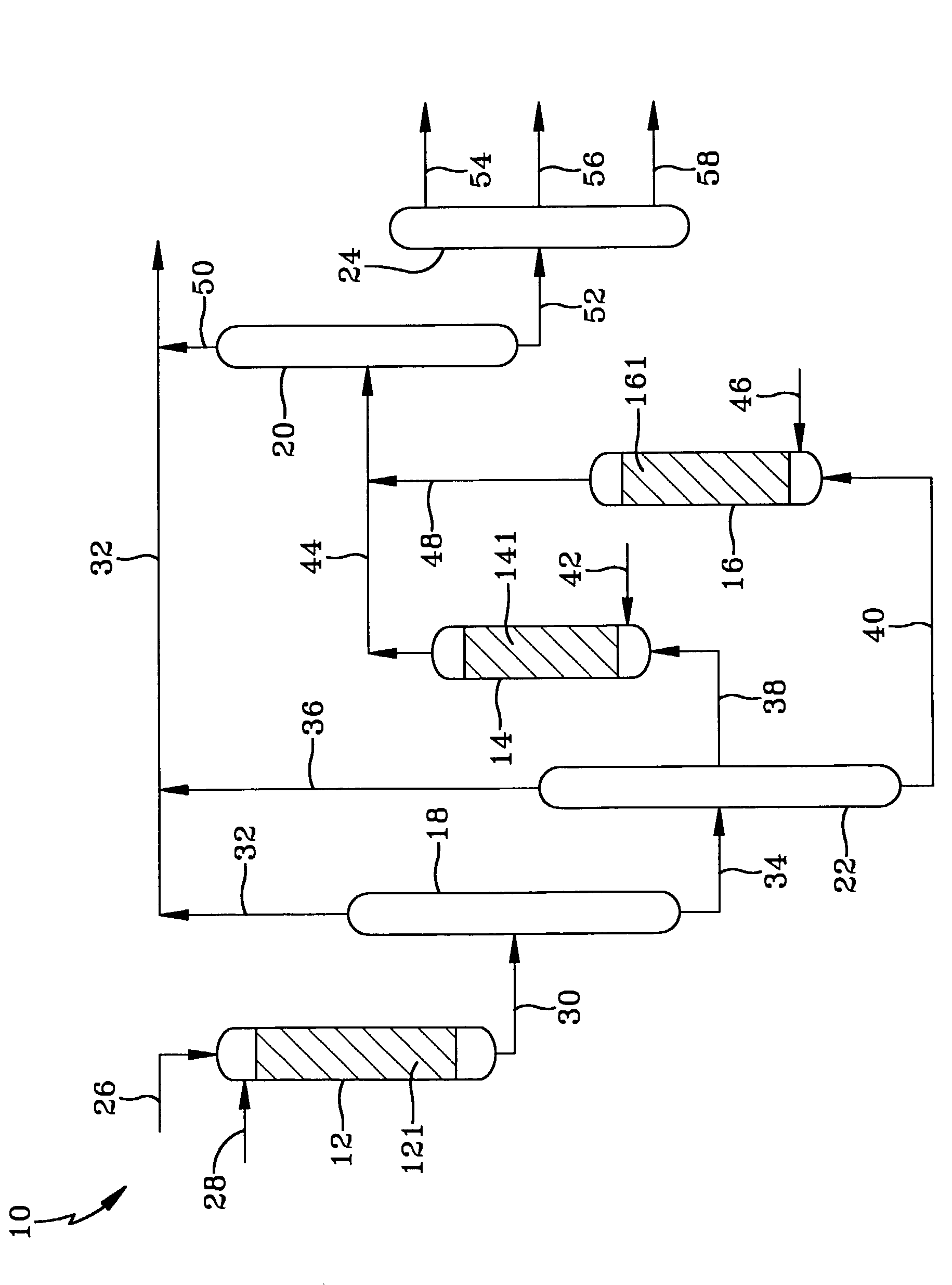
[0024]The Fischer-Tropsch wax used as a feed for the hydrodewaxing process of the invention comprised a 430° F.+ (221° C.) waxy hydrocarbon fraction produced in a slurry Fischer-Tropsch reactor, in which the H2 and CO were reacted in the presence of a titania supported cobalt rhenium catalyst to form hydrocarbons, most of which were liquid at the reaction conditions. The synthesis reactor was operating at conditions to produce to produce at least 14 pounds of 700° F.+ (371° C.+) hydrocarbons per 100 pounds of CO converted to hydrocarbons. This 430° F.+ (221° C.) wax comprised mostly normal paraffins, including 71.5 wt % of 700° F.+ (371° C.) hydrocarbons and 26.2 wt % of 1000° F.+ (538° C.) hydrocarbons. This raw (untreated) wax boiled continuously up to its end point of greater than 1050° F.+ (566° C.) and was fed directly into the first reactor, without any treatment. Three hydrodewaxing stages were used. Each of the three stages was an isothermal, up-flow, fixed bed reactor (R1, ...


PUM

PropertyMeasurementUnit
boiling pointaaaaaaaaaa

Abstract

Dewaxed fuel and lubricant base stocks are made by (a) producing a synthesis gas from natural gas, (b) reacting the H2 and CO in the gas in the presence of a cobalt Fischer-Tropsch catalyst, at reaction conditions effective to synthesize a waxy hydrocarbon feed boiling in the fuel and lubricant oil ranges, which is hydrodewaxed in a first stage to produce a dewaxed fuel and a partially dewaxed lubricant fraction. The partially dewaxed lubricant fraction is separated into heavy and lower boiling fractions each of which is separately hydrodewaxed, to produce lubricant base stocks. A hydrodewaxing catalyst comprising a hydrogenation component, binder and solid acid component used to hydrodewax at least one, and preferably at least two of the waxy feed and partially dewaxed heavy and lower boiling lubricant fractions.

Description

BACKGROUND OF THE DISCLOSUREField of the Invention[0001]The invention relates to producing fuels and lubricant oils from Fischer-Tropsch wax. More particularly the invention relates to a multi-stage process to produce fuels and lubricant oils from wax synthesized by reacting H2 and CO produced from natural gas in the presence of a cobalt Fischer-Tropsch catalyst, by hydrodewaxing the wax to produce dewaxed fuel and a partially dewaxed, heavier fraction in a first stage. The heavier fraction is split into light and heavy fractions boiling in the lubricant oil range, which are further hydrodewaxed in separate stages, to produce both light and heavy lubricant base stocks.BACKGROUND OF THE DISCLOSURE[0002]The relatively pure waxy and paraffinic hydrocarbons synthesized by the Fischer-Tropsch process are excellent sources of diesel fuel, jet fuel and premium lubricant oils with low sulfur, nitrogen and aromatics. When produced by a cobalt catalyst, the sulfur, nitrogen and aromatics cont...

Claims


Application Information

Patent Timeline
Patent Type & Authority Patents(United States)
IPC IPC(8): C10G47/02C07C5/13C10G35/04C10G2/00C10G65/04C10G65/16
CPCC10G2/32C10G65/16C10G2400/10C10G2/00C10G65/04
Inventor GENETTI, WILLIAM BERLINBISHOP, ADEANA RICHELLEPAGE, NANCY MARIEHOWSMON, GREGG JOHNSTONANSELL, LOREN LEONJOHNSON, JACK WAYNE
Owner EXXON RES & ENG CO
Why Eureka
Try Eureka