Controllable conduction device with electrostatic barrier

a conduction device and control technology, applied in the field of controllable conduction devices, can solve the problems of difficult device manufacture, unduly complicated fabrication of such capacitors, and achieve the effect of reducing the on/off current ratio

Inactive Publication Date: 2006-11-07
HITACHI LTD
View PDF37 Cites 7 Cited by
  • Summary
  • Abstract
  • Description
  • Claims
  • Application Information

AI Technical Summary

Benefits of technology

[0010]In accordance with the invention it has been appreciated that the charge barrier configuration can also be used in a controlled conduction device such as a transistor. The tunnel barrier configuration is used to provide a conductive path between a source and drain. When switched on, charge carriers can flow between the source and drain, but when switched off, the barrier configuration inhibits charge leakage through the path. A large on / off current ratio is thus obtained.

Problems solved by technology

However, the fabrication of such capacitors becomes unduly complicated.
However, this device is difficult to manufacture because the finger members formed in the gate need to be fabricated on a nanometer scale and current technologies do not permit such a device to be constructed readily on a scale small enough for operation at room temperature.

Method used


Image

  • Controllable conduction device with electrostatic barrier
  • Controllable conduction device with electrostatic barrier
  • Controllable conduction device with electrostatic barrier

Examples


further embodiment

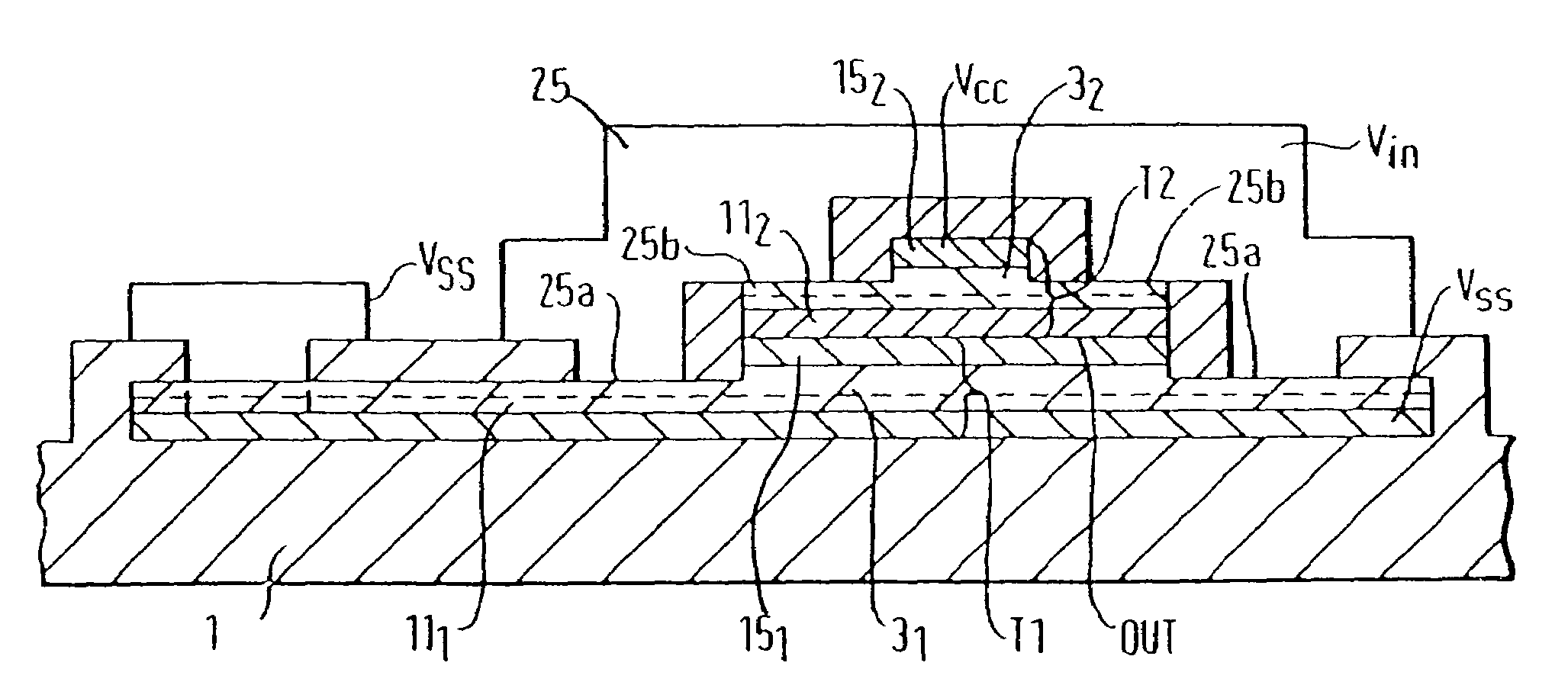
[0245]The structure described previously can also be arranged laterally as shown in FIGS. 42 and 43. The gate electrode 59G induces electric field into a multiple-tunnel junction to control the electron transport between a source and drain. The gate is not overlapped with source and drain contact regions and so in this structure, the gate region can be defined by lateral patterning and the fabrication process can be simplified.

[0246]A method of fabricating the device will now be described in more detail with reference to FIG. 43. The starting materials comprise a silicon wafer 56 which is thermally oxidised at 1000° C. to form a 600 nm thick layer 1 of SiO2 which acts as an insulating substrate. Then, a layer 2, which is used to produce the drain is formed on the SiO2 layer 1. The layer 2 comprises 100 nm thickness polysilicon deposited by LPCVD. A thin silicon dioxide layer of thickness of the order of 10 nm is deposited on the surface of the layer 2. Arsenic ions are then implante...


PUM


Abstract

A controllable conduction device in the form of a transistor comprises source and drain regions 5, 2 between which extends a conduction path P for charge carriers, a gate 4 for controlling charge carrier flow along the conduction path and a multiple layer structure 3 providing a multiple tunnel junction configuration in the conduction path, with the result that current leakage is blocked by the multiple tunnel junction configuration when the transistor is in its off state. Vertical and lateral transistor configurations are described, together with use of the transistor in complimentary pairs and for a random access memory cell. Improved gate structures are described which are also applicable to memory devices that incorporate the tunnel barrier configuration to store charge on the memory node.

Description

[0001]This is a division of application Ser. No. 09 / 710,868 filed 14 Nov. 2000 now abandoned, which is a division of application Ser. No. 09 / 492,171 filed Jan. 27, 2000, now U.S. Pat. No. 6,211,531, which is a division of application Ser. No. 09 / 095,058, filed Jun. 10, 1998, now U.S. Pat. No. 6,060,723, issued May 9, 2000.FIELD OF THE INVENTION[0002]This invention relates to a controllable conduction device with improved, reduced leakage current characteristics.BACKGROUND[0003]Integrated circuits have become progressively more miniaturised since their invention in 1959. Initially, their performance was improved by reducing the size of transistors used in the circuits, because the size reduction produced a reduction in parasitic capacitances of the circuit and a reduction in power dissipation. The miniaturisation was achieved by linearly scaling down the size of the features of the integrated circuit, by miniaturising the scale of the lithographic masks used in the manufacturing proc...

Claims


Application Information

Patent Timeline
Patent Type & Authority Patents(United States)
IPC IPC(8): H01L29/76H01L31/109G11C11/16H01L21/28H01L21/336H01L21/8242H01L21/8244H01L27/108H01L27/11H01L29/15H01L29/423H01L29/772H01L29/786H01L29/788H01L29/88
CPCB82Y10/00G11C11/16H01L21/28273H01L27/10808H01L27/1082H01L27/10858H01L27/10873H01L27/10876H01L27/11H01L29/154H01L29/42324H01L29/66825H01L29/772H01L29/78609H01L29/78618H01L29/78642H01L29/78687H01L29/7881H01L29/882H01L29/40114H10B12/33H10B12/31H10B12/036H10B12/05H10B12/053H10B10/00
Inventor NAKAZATO, KAZUOITOH, KIYOOMIZUTA, HIROSHISHIMADA, TOSHIKAZUSUNAMI, HIDEOTESHIMA, TATSUYAMINE, TOSHIYUKIYAMAGUCHI, KEN
Owner HITACHI LTD
Why Eureka
Try Eureka