Liquid crystal display apparatus having a transparent layer covering a reflective layer

a liquid crystal display and transparent layer technology, applied in non-linear optics, instruments, optics, etc., can solve the problems of insufficient contrast, inability to ensure and typical display quality such as color reproducibility and display brightness inferior to that of transmissive lcds, so as to prevent light coloring and improve display quality

Inactive Publication Date: 2006-11-07
SANYO ELECTRIC CO LTD
View PDF37 Cites 20 Cited by
  • Summary
  • Abstract
  • Description
  • Claims
  • Application Information

AI Technical Summary

Benefits of technology

[0018]The present invention was conceived to solve the above problem and advantageously provides a liquid crystal display apparatus in which the electrical characteristics of the first electrode and the second electrode with respect to the liquid crystal layer are matched so as to eliminate influence of flicker and parallax and to realize less coloring, high display quality, and low power consumption.
[0026]As described, by providing, on a side facing the liquid crystal layer on the first substrate side, a transparent first electrode having characteristics similar to those of the second electrode on the second substrate side and providing a reflective layer below the first electrode, it is possible to symmetrically drive the liquid crystal layer by the first and second electrodes. In particular, even when the driving frequency of the liquid crystal layer in each pixel is set to be lower than, for example, 60 Hz, it is possible to achieve a high quality display without generation of flicker or the like. In addition, by setting the thickness of the transparent first electrode to be 100 Å or less or 750 Å to 1250 Å, it is possible to prevent coloring and reduction in reflectance caused by the first electrode placed in front of the reflective layer.
[0028]As described, by providing, on a side of the first substrate facing the liquid crystal layer, a transparent first electrode having characteristics similar to those of the second electrode on the second substrate side and providing a reflective layer below the first electrode, it is possible for the liquid crystal layer to be symmetrically driven by the first and second electrodes. Here, a configuration wherein a difference between a work function of the transparent conductive material of the first electrode and a work function of a transparent conductive material of the second electrode formed on a side, facing the liquid crystal layer, of the second substrate is set to be 0.5 eV or less is particularly effective for symmetric driving. By employing such a configuration, even when the drive frequency of the liquid crystal layer in each pixel is set to be lower than, for example, 60 Hz, a high quality display can be achieved without generation of flicker or the like. In addition, according to the present invention, a structure is employed wherein a voltage for driving liquid crystal is applied to a transparent first electrode using a capacitive coupling via a reflective electrode connected to a switching element. With this structure, even though an electrode on the first substrate side is formed as a multi-layered structure of a reflective electrode and a transparent electrode, a structure similar to a conventional reflective liquid crystal display apparatus in which a metal reflective electrode is used as a pixel electrode can be used as the connection structure between the switching element and the reflective electrode. Therefore, it is possible to improve display quality and reduce power consumption with minimum design alteration.
[0032]According to another aspect of the present invention, it is preferable that, in the liquid crystal display device, the thickness of the transparent electrode to be capacitively coupled to the reflective electrode is in a range of 750 Å to 1250 Å or in a range from 1 Å to 100 Å. With such a thickness, it is possible to obtain high quality display without coloring.
[0036]As described, in addition to a liquid crystal display apparatus, in a light emitting display apparatus, by setting a thickness of a transparent electrode in a structure comprising a reflective layer and a transparent electrode layered on a substrate within a range from 750 Å to 1250 Å or within a range from 1 Å to 100 Å, it is possible to prevent coloring of light reflected by the reflective layer and emitted upwards from the element and to achieve higher quality display.

Problems solved by technology

Transmissive LCDs, however, have disadvantages in that power consumption is relatively high due to the light source which must continually illuminate, and that sufficient contrast cannot be ensured when the display is used in a bright environment, such as outdoors under daylight.
However, reflective LCDs suffer problems in that typical display quality such as reproducibility of color and display brightness is inferior to that of the transmissive LCDs.
However, in the reflective LCD as shown in FIG. 2, in which a reflective electrode formed by a metal material is used as the first electrode 150 and a transparent electrode formed by a transparent metal oxide material such as ITO is used as the second electrode 250, certain problems such as display flicker and image persistence in the liquid crystal layer may occur depending on the drive conditions.
These problems are noticeable when the liquid crystal is driven at a frequency less than the critical flicker frequency (CFF), for example, as has been reported recently.
It has been revealed, however, that when each pixel of a conventional reflective liquid crystal panel is driven at a frequency less than the CFF, the above-described problems of flicker and image persistence in the liquid crystal layer are significant, which leads to significant deterioration in display quality.
Such a difference of charge induced on the interface between the liquid crystal and the alignment film at each electrode side would in turn cause impurity ions or the like to be unevenly located toward one of the first and second electrodes within the liquid crystal layer, which results in accumulation of remaining DC voltage in the liquid crystal layer 300.
As the liquid crystal drive frequency is lowered, the influence of this remaining DC voltage on the liquid crystal increases and generation of flicker and image persistence in the liquid crystal layer become more significant.
Accordingly, driving the liquid crystal at a frequency less than the CFF, in particular, is substantially difficult.
When a reflector is thus provided on the outer side of the first substrate, however, the length of a light path is increased by an amount corresponding to the thickness of the transparent first electrode 150 and of the transparent first substrate, thereby making the display quality likely to deteriorate due to parallax.
Consequently, in reflective LCDs which demand high display quality, a reflective electrode is employed as a pixel electrode, and it is therefore impossible to reduce the drive frequency so as to achieve lower power consumption, because flicker or the like is generated at the lower drive frequency, as described above.

Method used


Image

  • Liquid crystal display apparatus having a transparent layer covering a reflective layer
  • Liquid crystal display apparatus having a transparent layer covering a reflective layer
  • Liquid crystal display apparatus having a transparent layer covering a reflective layer

Examples


first embodiment

[0088]As described, even when a reflective layer must be formed on one of the substrate sides such as in reflective LCDs and in transflective LCDs, a first electrode and a second electrode having similar characteristics can be disposed in equivalent positions with respect to the liquid crystal layer. By setting the thickness of the transparent first electrode to 100 Å or less or approximately 750 Å to 1250 Å, it is possible to prevent coloring and reduction in reflectance caused by the first electrode disposed in front of the reflective layer. In addition, by increasing the thickness within the range described above, it is possible to reduce the resistance of the first electrode and prevent disconnection. Therefore, it is possible to symmetrically AC drive the liquid crystal and, at the same time, a high quality display can be realized.

[0089]Referring to the drawings, a second preferred embodiment of the present invention will now be described in which a transparent electrode 50 is...

second embodiment

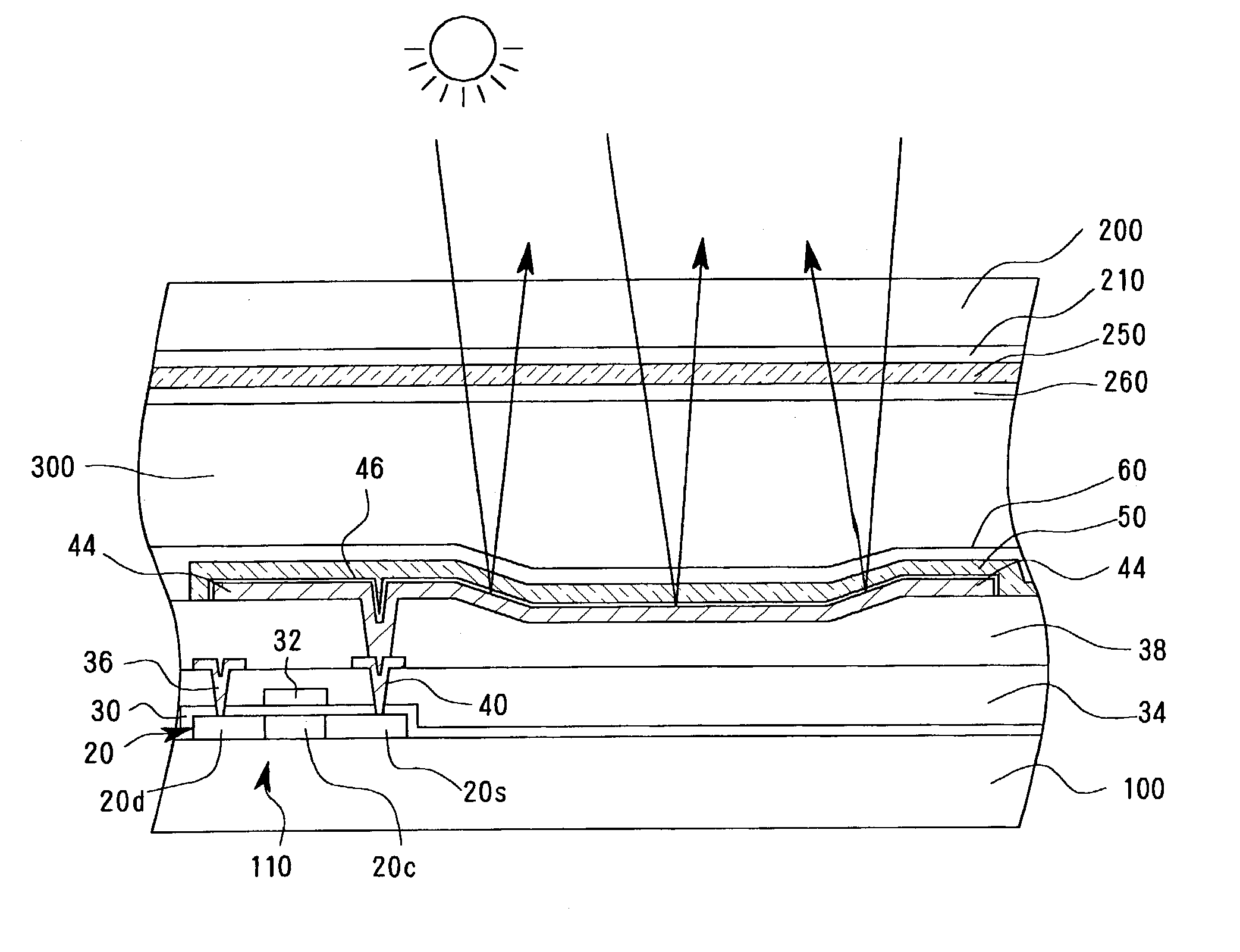
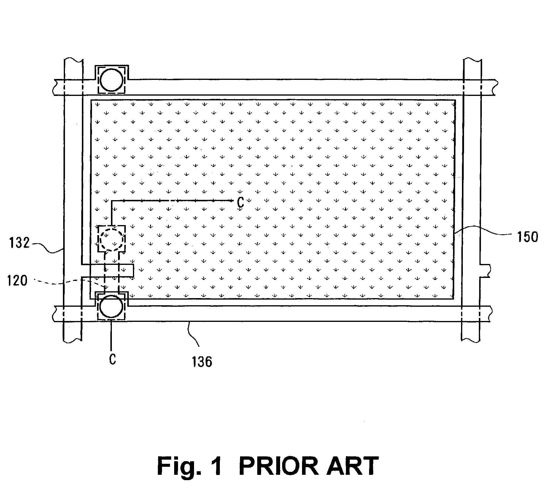
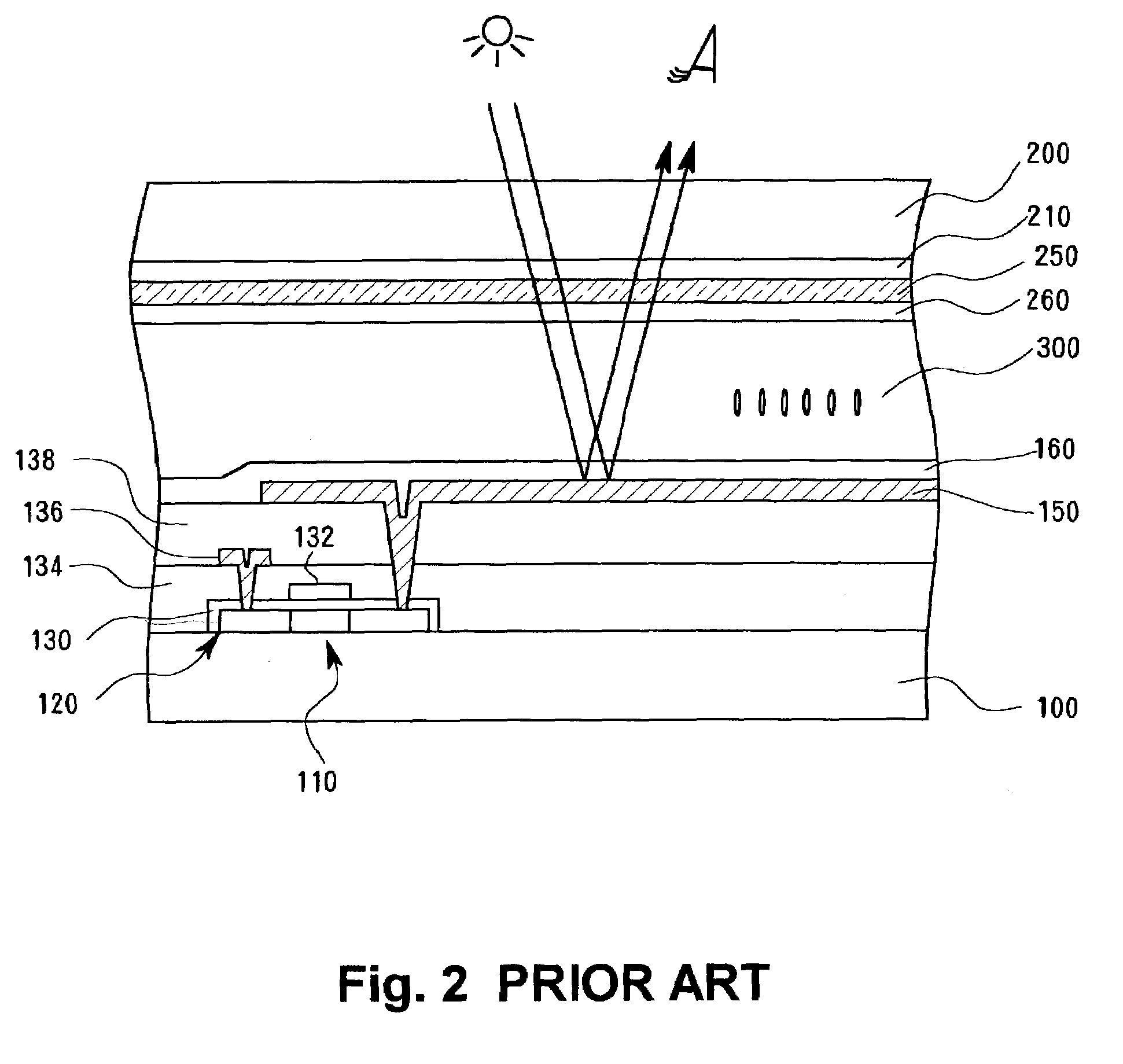
[0090]FIG. 10 shows a portion of a planar structure of a first substrate side of a reflective active matrix LCD as an example reflective LCD according to the FIG. 11 schematically shows a cross sectional structure of the LCD along the line A—A of FIG. 10. In these drawings, components already described above will be assigned the same reference numerals and will not be further described. A difference from the structure described above is that a reflective electrode 44 made of a reflective metal material and respectively formed on a planarization insulating film 38 is connected to a TFT 110 (in this example structure, a source electrode of the TFT 110) and a transparent first electrode 50 made of a transparent conductive material is formed in an individual pattern above the reflective electrode 44 with an insulating film 46 between the electrodes 44 and 50.

[0091]When a gate signal (scan signal) is applied to agate electrode 32 of the TFT 110, the TFT 110 is switched on, causing, for ...


PUM

PropertyMeasurementUnit
drive frequencyaaaaaaaaaa
driving frequencyaaaaaaaaaa
work functionaaaaaaaaaa

Abstract

A reflective layer for reflecting light incident from a second substrate side and transmitting through a second electrode made of ITO or the like is formed above a first substrate, a switching element provided for each pixel, and an insulating film covering the switching element, the reflective layer being insulated from the switching element. A first electrode having a work function similar to the second electrode and made of a transparent conductive material such as ITO is formed more proximate to a liquid crystal layer than is the reflective layer and is connected to the switching element. The thickness of the first electrode is set to 100 Å or less or in a range approximately from 750 Å to 1250 Å. Alternatively, the switching element maybe connected to the reflective electrode, the first electrode and the reflective electrode which are formed with an insulating film therebetween may be capacitively coupled, and the first electrode may be driven by the reflective electrode via the capacitor.

Description

BACKGROUND OF THE INVENTION[0001]1. Field of the Invention[0002]The present invention relates to a structure in a reflective liquid crystal display apparatus or a transflective liquid crystal display apparatus which has reflective functionality.[0003]2. Description of the Related Art[0004]Liquid crystal display apparatuses (hereinafter referred to as “LCDs”) are advantageous in that they are thin and consume relatively little power, and are now widely used for computer monitors and monitors for portable information devices or the like. In LCDs, liquid crystal is sealed between a pair of substrates each having an electrode formed thereon, and the alignment of the liquid crystal disposed between these electrodes is controlled by these electrodes to thereby create a display. However, unlike CRT (Cathode Ray Tube) displays, electroluminescence (hereinafter referred to as “EL”) displays, or the like, LCDs require a light source in order to display an image for viewer observation, because...

Claims


Application Information

Patent Timeline
Patent Type & Authority Patents(United States)
IPC IPC(8): G02F1/1343G02F1/1335
CPCG02F1/133553G02F1/133555G02F1/1335
Inventor OGAWA, SHINJIINOUE, KAZUHIROKOMA, NORIOODA, NOBUHIKOISHIDA, SATOSHIYAMADA, TSUTOMUYAMASHITA, TOHRU
Owner SANYO ELECTRIC CO LTD
Why Eureka
Try Eureka