Method and apparatus for controlling an instrumentation system

a technology of instrumentation system and control software, which is applied in the direction of instruments, execution of user interfaces, static indicating devices, etc., can solve the problems of user force, difficult instrument connection/communication and instrument response parsing, and laborious acquisition and analysis of data in such instrumentation systems

Active Publication Date: 2006-11-07
NATIONAL INSTRUMENTS
View PDF3 Cites 44 Cited by
  • Summary
  • Abstract
  • Description
  • Claims
  • Application Information

AI Technical Summary

Benefits of technology

[0026]In one embodiment, a task object may be generated in response to user input. The user may then graphically add the task object to an instrument control application program. The user may invoke a user interface for graphically editing the task object. The user may then graphically generate one or more query blocks using the user interface. Each query block may be executable within an instrumentation system to connect with a message-based instrument, send a query message to the message-based instrument, receive a response to the query message from the message-based instrument, parse the response, and output results of said parsing the response. The user may then graphically add the one or more query blocks to the task object.

Problems solved by technology

Acquisition and analysis of data in such instrumentation systems was tedious and error prone.
Therefore, implementation of such systems frequently requires the involvement of a programmer to develop software for acquisition, analysis and presentation of instrumentation data.
Also, there may be users of an instrumentation system who do not want the complications that are inherent with learning to use a driver or that do not have access to a driver.
Thus, in many cases the user may be forced to write mini instrument drivers with the desired subset instrument functionality.
Both instrument connection / communication and instrument response parsing are difficult and time-consuming tasks.

Method used


Image

  • Method and apparatus for controlling an instrumentation system
  • Method and apparatus for controlling an instrumentation system
  • Method and apparatus for controlling an instrumentation system

Examples


Embodiment Construction

[0042]The preferred embodiment of the invention is adapted for instrumentation control systems. However, it is noted that the method and apparatus of the present invention discloses a software architecture model that has numerous other applications in any of a number of fields. The following disclosure describes the preferred embodiment of the invention in an instrumentation control system application.

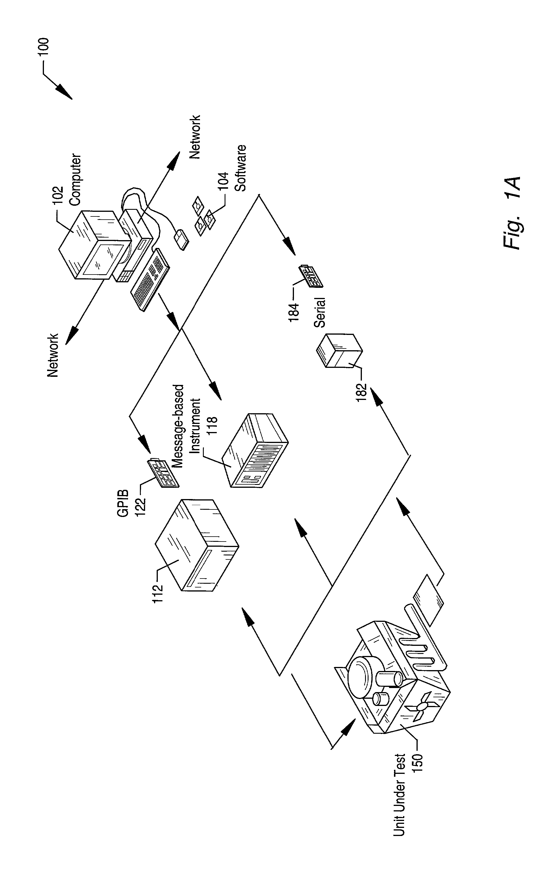
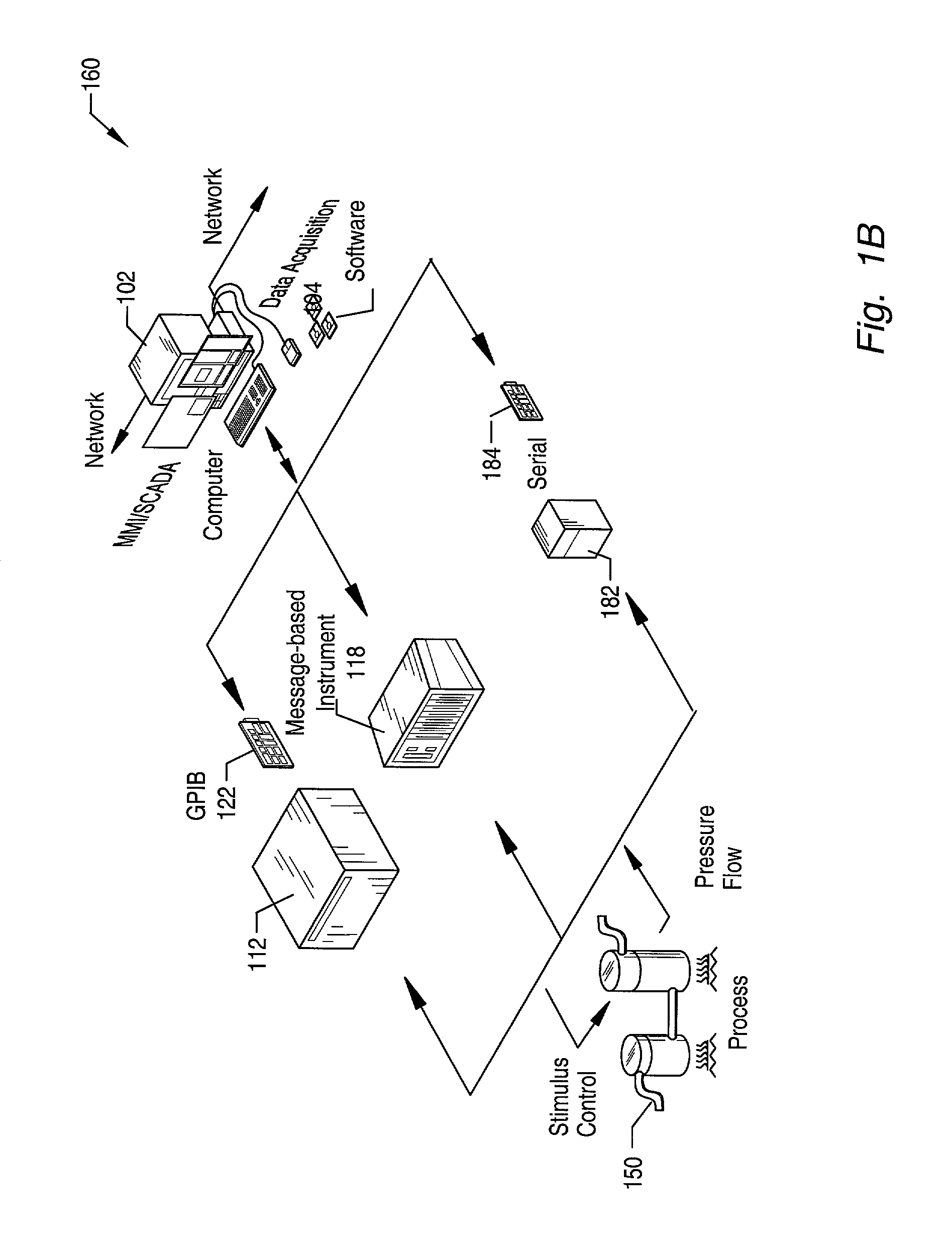
FIGS. 1A and 1B—Instrumentation and Industrial Automation Systems

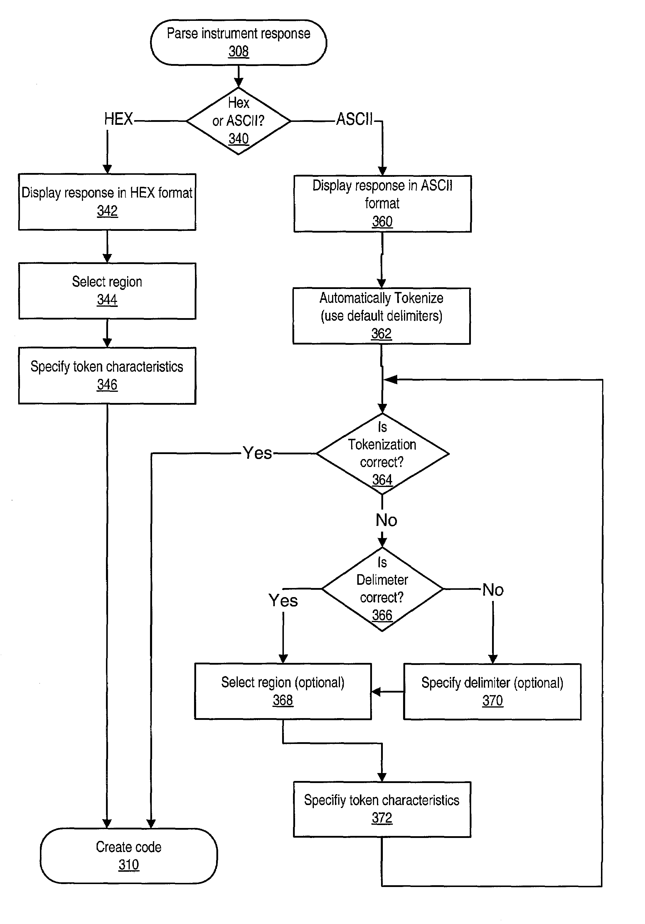
[0043]The following describes embodiments of the present invention involved with performing test and / or measurement functions and / or controlling and / or modeling instrumentation or industrial automation hardware. The system and method of the present invention may assist the user in parsing data such as instrument responses without forcing the user to write parsing code. The data may be of any of a variety of types of data including, but not limited to, ASCII data and binary data.

[0044]It is noted that the present invention...


PUM


Abstract

An instrument I/O assistant and the algorithms that may be used to manage instrument responses and that may provide an instrument-centric approach to message-based instrument I/O. The instrument I/O assistant may assist the user in parsing instrument responses by offering an environment to interact with an instrument response without forcing the user to write parsing code. Embodiments may be integrated into instrumentation control programs to make instrument I/O as transparent as possible. The instrument I/O assistant may provide code generation so that the parsing of an instrument response performed in the instrument I/O assistant can be reused. The saved code for one query and response may be referred to as a query block. Two or more query blocks may be saved into a task. A task is a series of executable query blocks. The task may be executed, or alternatively code may be generated to execute the task.

Description

PRIORITY CLAIM[0001]This application claims benefit of priority of U.S. provisional application Ser. No. 60 / 312,257 titled “Method and Apparatus for Controlling an Instrumentation System” filed Aug. 14, 2001, whose inventors are David W Fuller III, Christopher G. Cifra and Thomas V. Connell Jr.FIELD OF THE INVENTION[0002]The present invention relates to I / O control software for instrumentation systems, and more particularly to a system and method for querying message-based instruments, parsing the responses, and generating code that encapsulates the connection / communication with the instrument and the parsing of the response.DESCRIPTION OF THE RELATED ART[0003]An instrument is a device that collects data or information from an environment or unit under test and displays this information to a user. An instrument may also perform various data analysis and data processing on acquired data prior to displaying the data to the user. Examples of various types of instruments include oscillo...

Claims


Application Information

Patent Timeline
Patent Type & Authority Patents(United States)
IPC IPC(8): G06F13/00G06F15/00G06F9/44G09G5/00
CPCG06F8/34G06F9/4443G06F9/451
Inventor FULLER, III, DAVID WCIFRA, CHRISTOPHER G.CONNELL, JR., THOMAS V.
Owner NATIONAL INSTRUMENTS
Why Eureka
Try Eureka