

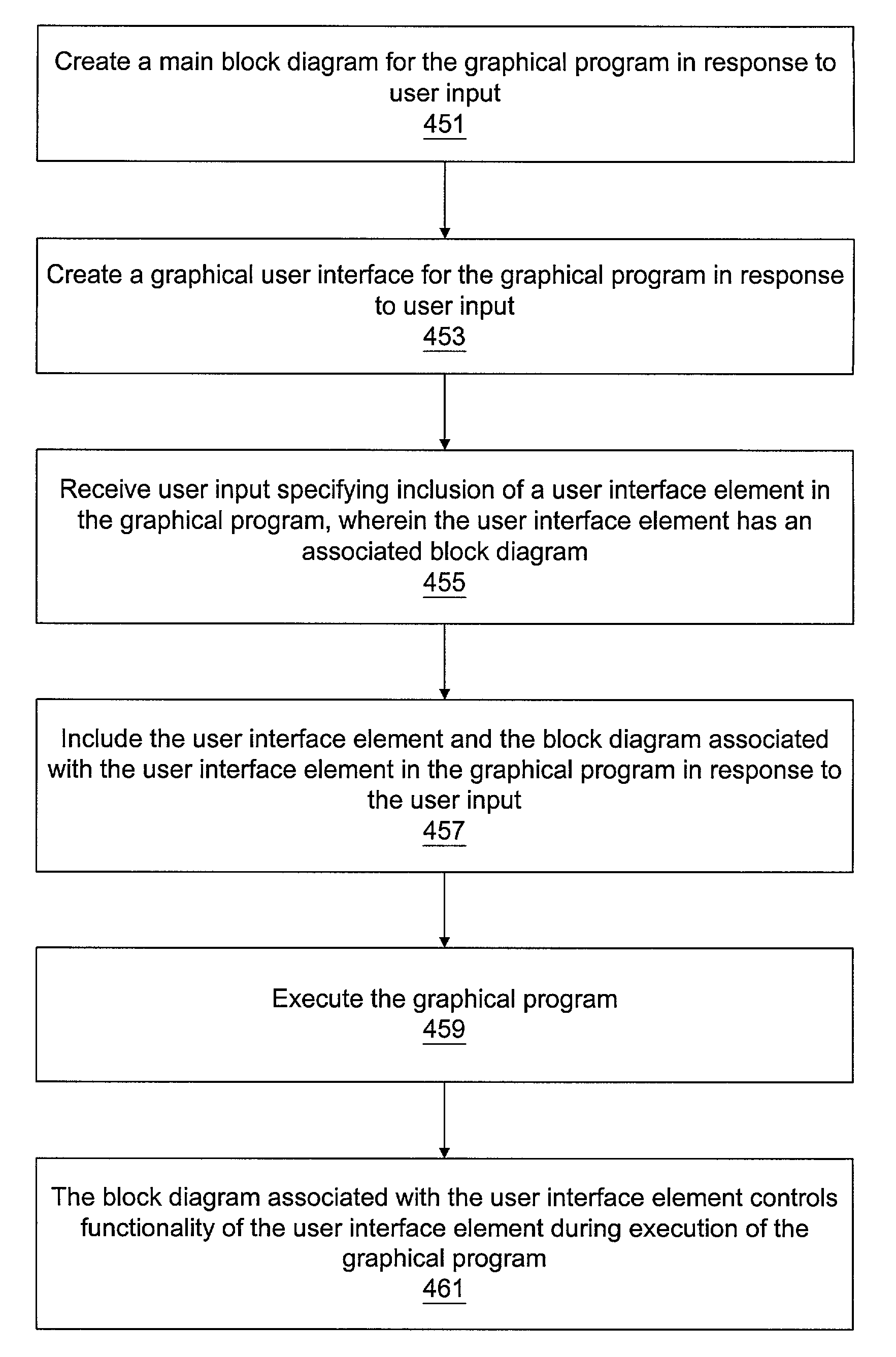
System and method for associating a block diagram with a user interface element
a user interface and element technology, applied in the field of system and method for associating a block diagram with an interface element, can solve the problems of simple or very complex operation of the block diagram, and achieve the effect of increasing the number and types of user interface elements available, increasing code modularity and reusability
- Summary
- Abstract
- Description
- Claims
- Application Information
AI Technical Summary
Benefits of technology
Problems solved by technology
Method used
Image

Examples
Embodiment Construction
Incorporation by Reference
[0037]The following references are hereby incorporated by reference in their entirety as though fully and completely set forth herein:
[0038]U.S. Pat. No. 4,914,568 titled “Graphical System for Modeling a Process and Associated Method,” issued on Apr. 3, 1990.
[0039]U.S. Pat. No. 5,481,741 titled “Method and Apparatus for Providing Attribute Nodes in a Graphical Data Flow Environment”.
[0040]U.S. Pat. No. 6,173,438 titled “Embedded Graphical Programming System” filed Aug. 18, 1997.
[0041]U.S. Pat. No. 6,219,628 titled “System and Method for Configuring an Instrument to Perform Measurement Functions Utilizing Conversion of Graphical Programs into Hardware Implementations,” filed Aug. 18, 1997.
[0042]U.S. patent application Ser. No. 09 / 617,600 now U.S. Pat. No. 6,802,053 titled “Graphical Programming System with Distributed Block Diagram Execution and Front Panel Display,” filed Jun. 13, 2000.
[0043]U.S. patent application Ser. No. 09 / 745,023 titled “System and Met...
PUM
 Abstract
Description
Claims
Application Information